

Diffractive optical element for shaping gauss beam into flat-topped beam, and preparation method thereof
A diffractive optical element and flat-hat beam technology, which is applied in the field of diffractive optical element and its preparation, can solve problems such as complex manufacturing process, achieve high energy transmittance, simple installation and use, and flexible use
- Summary
- Abstract
- Description
- Claims
- Application Information
AI Technical Summary
Problems solved by technology
Method used
Image

Examples
Embodiment 1
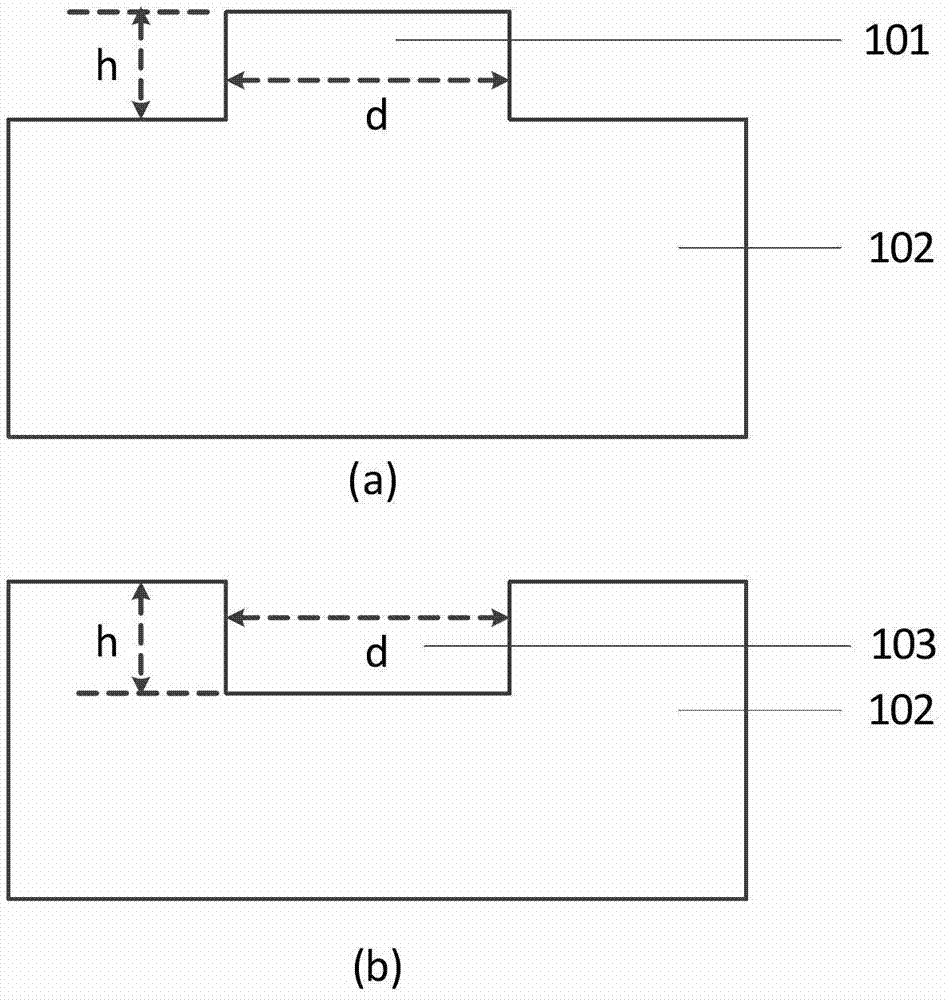
[0050] Example 1: Realizing the DOE (groove type) of the square top spot
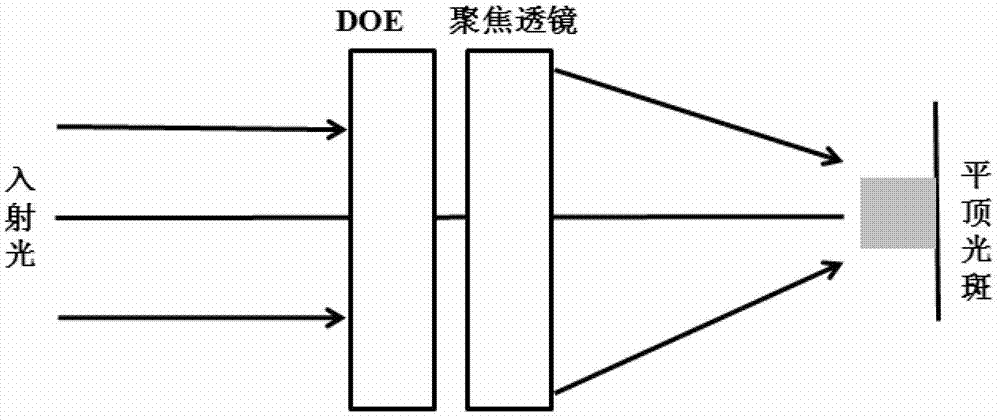
[0051] There is a laser incident light source with a wavelength of 532nm and a spot diameter of 2mm. According to the DOE requirements, a square flat-top spot with a side length of 200um can be obtained under a focusing lens with a focal length of 200mm. In order to obtain the best shaping effect, the incident light source needs to be expanded and collimated to a diameter of about 6mm.
[0052] The implementation steps are as follows:
[0053] The first step is to carry out theoretical simulation design according to the above requirements, and generate a GDS file. The side length of the square groove in the GDS file is 4mm;
[0054] In the second step, the photoresist is spin-coated on the photoresist mask plate evaporated with metal chromium, and then the photoresist is exposed according to the GDS file using the mask plate preparation equipment;
[0055] The third step is to develop and fix the exp...
Embodiment 2
[0064] Example 2: Realize the DOE of the square flat top spot (step type)
[0065] There is a laser incident light source with a wavelength of 532nm and a spot diameter of 2mm. According to the DOE requirements, a square flat-top spot with a side length of 200um can be obtained under a focusing lens with a focal length of 200mm. In order to obtain the best shaping effect, the incident light source needs to be expanded and collimated to a diameter of about 6mm.
[0066] Implementation steps refer to embodiment 1, the difference is:
[0067] The first step is to carry out theoretical simulation design according to the above requirements, and generate a GDS file. The side length of the square step in the GDS file is 4mm;
[0068] The seventh step is to use the prepared photolithographic mask to expose, develop and fix the photoresist on the quartz substrate, so as to obtain a photoresist pattern consistent with the designed GDS file on the quartz substrate;
[0069] The 8th st...
Embodiment 3
[0071] Embodiment 3 Realize the DOE (groove type) of circular flat top spot:
[0072] There is a laser incident light source with a wavelength of 532nm and a spot diameter of 2mm. According to DOE requirements, a circular flat-top spot with a diameter of 200um can be obtained under a focusing lens with a focal length of 200mm. In order to obtain the best shaping effect, the incident light source needs to be expanded and collimated to a diameter of about 6mm.
[0073] Implementation steps refer to embodiment 1, the difference is:
[0074] The first step is to carry out theoretical simulation design according to the above requirements, and generate a GDS file. The diameter of the circle in the GDS file is 4mm;
[0075] The 8th step, as described in embodiment 1, difference is that what obtain is that diameter is the circular groove of 4mm;
[0076] All the other steps are the same as in Example 1.
PUM
| Property | Measurement | Unit |
|---|---|---|
| Wavelength | aaaaa | aaaaa |
| Diameter | aaaaa | aaaaa |
| Diameter | aaaaa | aaaaa |
Abstract
Description
Claims
Application Information