Air-cooled fuel cell system and coupling heat control method thereof

A fuel cell system and fuel cell technology, applied in the direction of fuel cell heat exchange, fuel cells, fuel cell additives, etc., can solve problems such as heat loss, operation (difficult to start, increase air flow, etc.), to achieve good environmental adaptability, The effect of shortening hydrogen charging time and reducing air flow

Inactive Publication Date: 2013-11-20
SOUTHWEST JIAOTONG UNIV
View PDF8 Cites 16 Cited by
  • Summary
  • Abstract
  • Description
  • Claims
  • Application Information

AI Technical Summary

Problems solved by technology

[0007] However, the existing technology does not consider the impact of environmental conditions on the fuel cell system, and its thermal control methods cannot be adjusted with changes in environmental conditions to maintain stable and efficient operation of the system.
For example, when the ambient temperature is low, the hydrogen storage device needs heat to release hydrogen, and the normal operation of the fuel cell also requires a certain amount of heat to maintain a suitable working temperature. The existing passive heat control method through the coupling of the alloy hydrogen storage device and the fuel cell structure There are obvious shortcomings. While the hydrogen storage device releases hydrogen, it has been continuously absorbing the heat generated by the fuel cell. If the battery is in the low-power operation stage (such as the start-up stage), the heat generated by the battery is not much. The heat is absorbed by the hydrogen storage device, which is not enough to maintain the normal working temperature, causing the fuel cell temperature to be too low and difficult to operate (start); and because the heat absorbed by the hydrogen storage alloy is not completely equal to the heat generated by th...

Method used


Image

  • Air-cooled fuel cell system and coupling heat control method thereof
  • Air-cooled fuel cell system and coupling heat control method thereof
  • Air-cooled fuel cell system and coupling heat control method thereof

Examples


Embodiment Construction

[0023] Exemplary embodiments of the present invention will become apparent from the ensuing detailed description, and it should be understood that while disclosing exemplary embodiments of the present invention, the specific examples in the detailed description are for illustration purposes only, and should not be regarded as the basis for the present invention. limit range.

[0024] The specific embodiments of the present invention will be further described below in conjunction with the accompanying drawings.

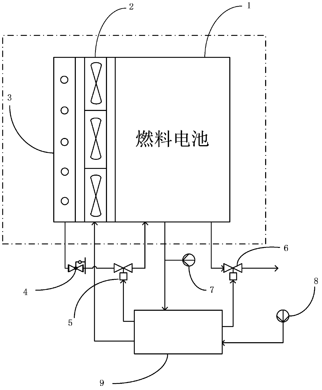
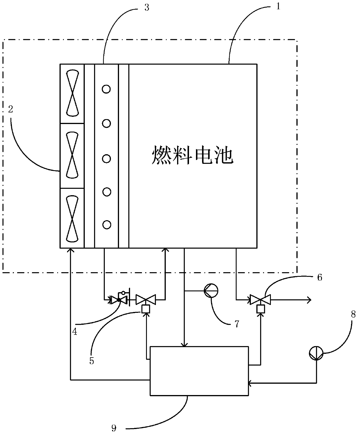
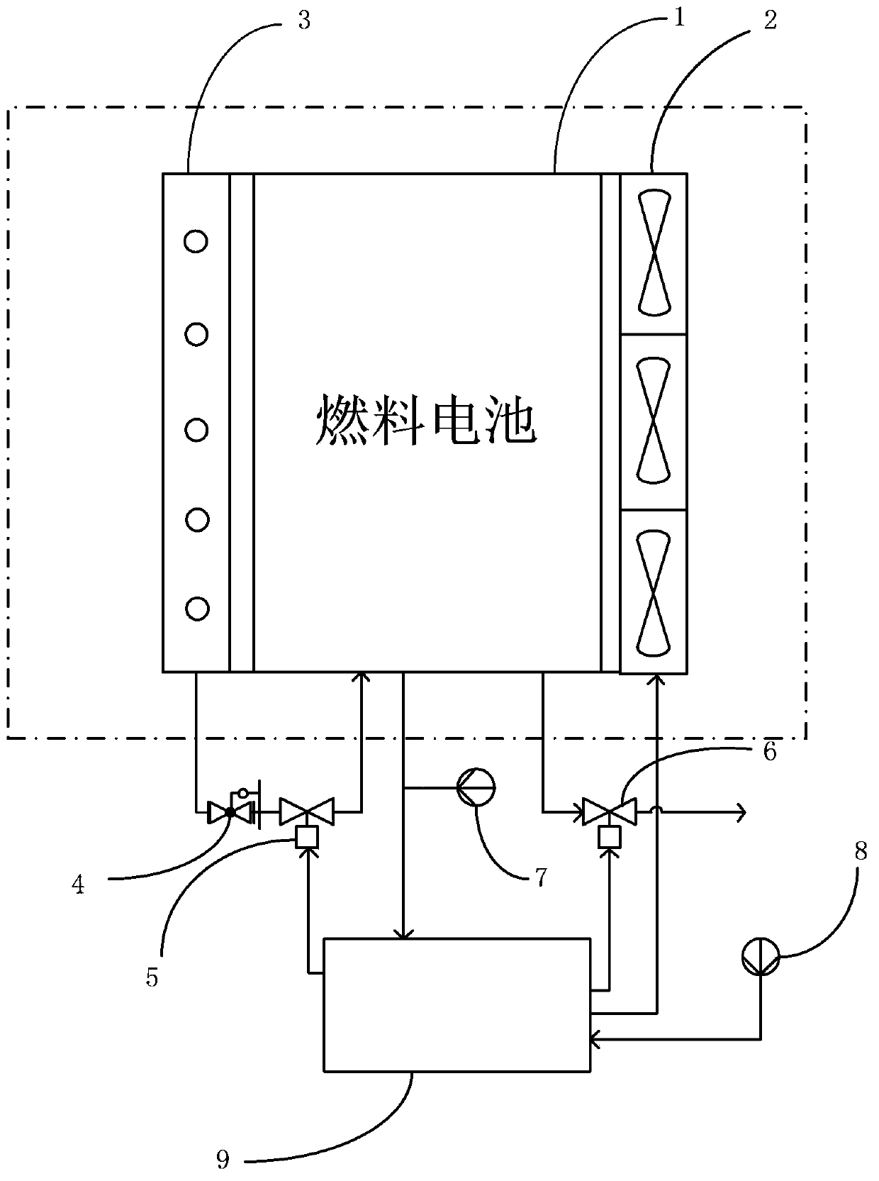
[0025] The air-cooled fuel cell system coupling thermal control method provided by the present invention can be achieved by figure 1 The fuel cell system shown is realized as figure 1The fuel cell system shown includes at least one fuel cell or fuel cell stack 1, at least one fuel cell fan 2, at least one hydrogen storage device or hydrogen storage stack 3, a fuel cell temperature sensor 7, an ambient temperature sensor 8, and a controller 9 And pressure reducing val...


PUM


Abstract

The invention discloses an air-cooled fuel cell system and a coupling heat control method thereof. The method comprises the following steps of: acquiring the current environment temperature of a fuel cell; acquiring the current working temperature of the fuel cell; controlling the rotation direction of a fuel cell fan according to the environment temperature; and controlling the rotation speed of the fuel cell fan according to the working temperature of the fuel cell. The rotation direction and rotation speed of the cooling fan are controlled according to the acquired working temperature and environment temperature of the fuel cell by virtue of the heat coupling characteristic of hydrogen desorption for heat absorption of an alloy hydrogen storage container and reaction for heat release of the fuel cell, so that effective coupling heat control over the hydrogen storage container and the fuel cell is realized, the hydrogen desorption efficiency of the hydrogen storage container at low environment temperature can be improved, the working conditions of the fuel cell at high environment temperature are improved, and the environmental adaptability of the air-cooled fuel cell system is further improved.

Description

technical field [0001] The invention relates to the field of fuel cells, in particular to a heat control method coupled with an air-cooled fuel cell system. Background technique [0002] A fuel cell is a power generation device that converts the chemical energy of the reacting substances into electrical energy through an electrochemical reaction. Since its power generation process does not involve the combustion of fuel, it is not limited by the Carnot cycle and has high energy conversion efficiency. Fuel cells generally use As a reactive substance, hydrogen and oxygen also have the advantages of high power density and energy density, clean and efficient, and a wide power range. They have broad application prospects in mobile power supplies, household power supplies, transportation, distributed power stations, and submarines. [0003] Fuel cells convert chemical energy into electrical energy using an electrochemical reaction, which is an exothermic reaction that produces ele...

Claims


Application Information

Patent Timeline
IPC IPC(8): H01M8/04H01M8/04014H01M8/04701
CPCY02E60/50
Inventor 彭赟彭飞刘志祥李奇陈维荣戴朝华
Owner SOUTHWEST JIAOTONG UNIV
Why Eureka
Try Eureka