Balanced switching control circuit for battery management system

A battery management system and control circuit technology, applied in the direction of battery circuit devices, circuit devices, collectors, etc., can solve the problems of high switch cost, cost increase, high cost of switching switches, etc., to facilitate popularization and application, and reduce withstand voltage requirements Effect

Active Publication Date: 2013-11-20
SHENZHEN KELIE TECH
View PDF2 Cites 4 Cited by
  • Summary
  • Abstract
  • Description
  • Claims
  • Application Information

AI Technical Summary

Problems solved by technology

[0003] The changeover switch is one of a solid-state relay and a mechanical relay including a Metal Oxide Semiconductor Field Effect Transistor (Metal Oxide Semiconductor Field Effect Transistor, abbreviated as MOSFET), and its cost varies with the on-resistance/withstand voltage of the device. The geometric progression rises, the on-resistance is small, and the switch cost of the equalizer with high withstand voltage is relatively high. Choosing a switch with low withstand voltage can effectively reduce the cost, but there is a risk of breakdown, especially for those connected to the last battery cell. The MOSFET in the solid-state relay of the MOSFET needs to withstand a withstand

Method used


Image

  • Balanced switching control circuit for battery management system
  • Balanced switching control circuit for battery management system

Examples


Example Embodiment

[0031] The present invention will be described below in combination with specific embodiments and with reference to the accompanying drawings.

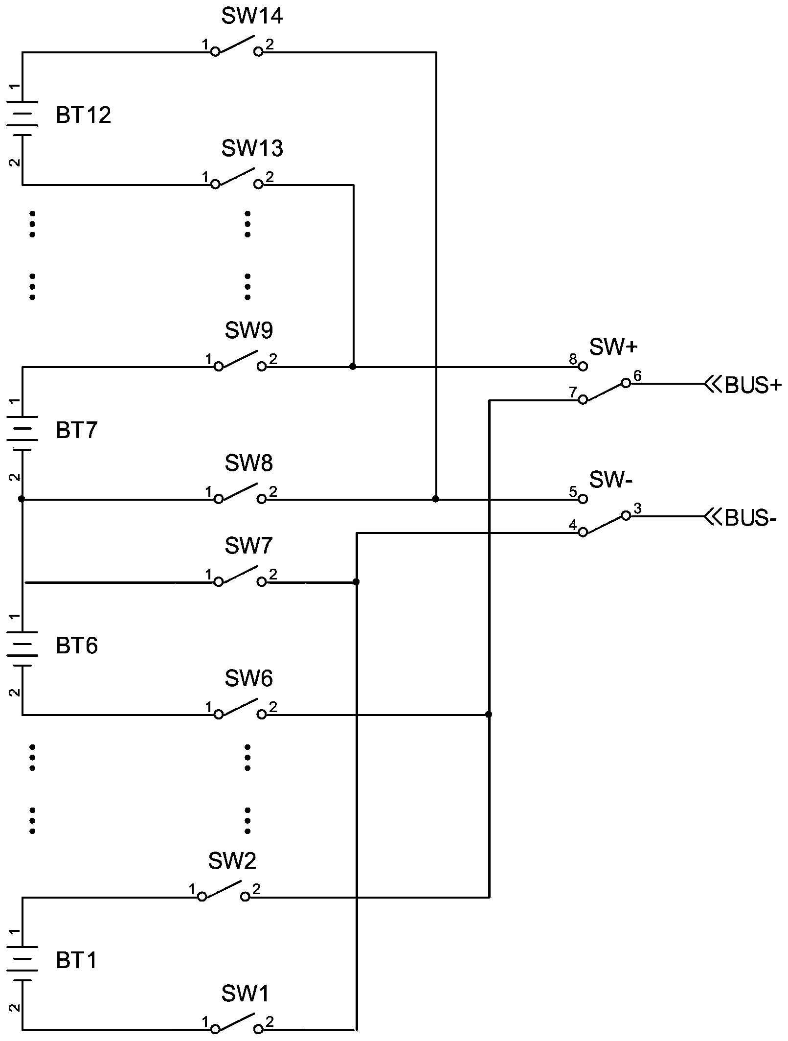
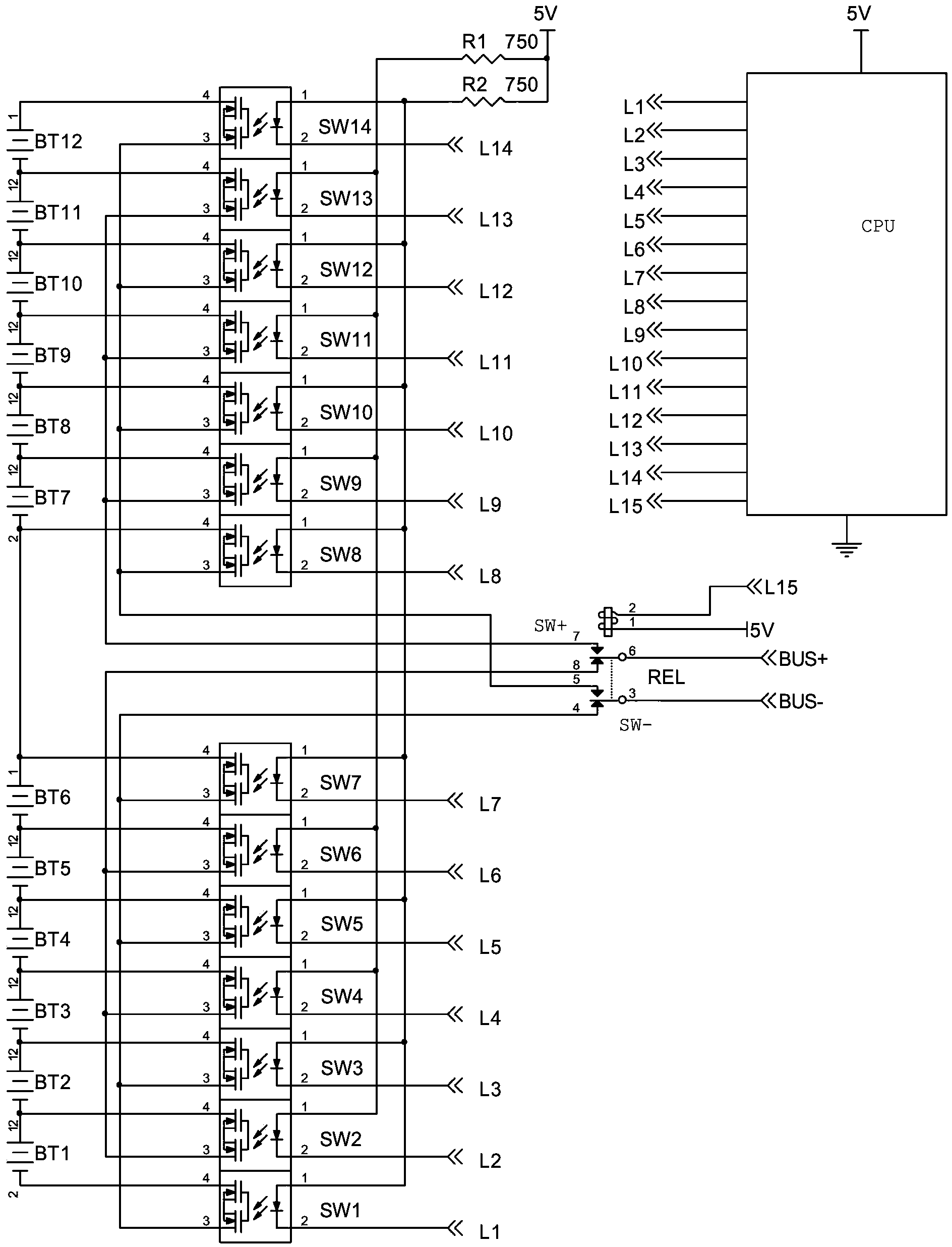
[0032] a kind of like figure 1 , 2In the balanced switching control circuit used in the battery management system shown, the battery cells used to form a series battery pack are lithium iron phosphate batteries BT1 to BT12 with a number of 12 cells, a capacity of 1000AH, and a rated voltage of 3.5V, where The battery cells BT1~BT6 form the lower half series battery group from bottom to top in series order, and the battery cells BT7~BT12 form the upper half series battery group from bottom to top in series order, the first battery of the lower half series battery group The negative pole of the single cell BT1 is the negative pole of the lower half of the series battery group, which is also the negative pole of the series battery group. The positive pole of the last battery cell BT12 of the upper half of the series battery group is the...


PUM


Abstract

The invention discloses a balanced switching control circuit for a battery management system. The balanced switching control circuit is characterized by comprising a backward stage switching switch group, a preceding stage lower half switching switch group, a preceding stage upper half switching switch group, and a CPU (Central Processing Unit), wherein the backward stage switching switch group is formed by a backward stage lower switching switch and a backward stage upper switching switch; the number of switches of the preceding stage lower half switching switch group is one more than units of battery cells forming a lower half series battery group; and the number of switches of the preceding stage upper half switching switch group is one more than units of battery cells forming an upper half series battery group. The backward stage switching switch group is a bipolar on-off switching switch, static contacts of the backward stage lower switching switch and the backward stage upper switching switch are respectively connected with balanced BUS- and balanced BUS+, controlled terminals of all the switching switches are connected with the CPU, the CPU sends a command to control the switching, and one battery cell needs to be balanced is switched to be connected onto the balanced BUS+ and BUS- so as to be connected with a discharging and charging module. According to the circuit, the withstand voltage requirement of the switching switches is reduced by half, and low-voltage switching switches are beneficial for being popularized and applied in battery balanced circuits with multiple strings.

Description

technical field [0001] The invention relates to a battery management system, in particular to a balanced switching control circuit for the battery management system. Background technique [0002] The battery pack composed of new batteries including lithium-ion batteries connected in series, due to the inconsistency of the battery cells, will lead to a decrease in the available capacity of the entire battery pack when used; charging a battery cell with a high voltage will cause the charging process to advance Termination, so that the charging capacity becomes smaller; when the battery cell with low voltage is discharged, it will cause the discharge process to terminate early, so that the discharge capacity is reduced. An equalizer or equalization circuit module is set in the battery management system (Battery management system, abbreviated as BMS) to balance the battery cells, discharge the cells with high voltage, and charge the cells with low voltage, which can Effectively...

Claims


Application Information

Patent Timeline
IPC IPC(8): H02J7/00
Inventor 张志国张泱渊仝瑞军
Owner SHENZHEN KELIE TECH
Why Eureka
Try Eureka