Plasma arc starting circuit

A plasma and circuit technology, applied in the direction of plasma, electrical components, and conversion equipment without intermediate conversion to AC, can solve the problems of complex switching circuit structure and high withstand voltage of devices, so as to achieve simple and reliable modules and reduce overall weight Effect

Inactive Publication Date: 2013-11-20
SHENZHEN AEROSPACE NEW POWER TECH
View PDF5 Cites 6 Cited by
  • Summary
  • Abstract
  • Description
  • Claims
  • Application Information

AI Technical Summary

Problems solved by technology

[0005] In order to solve the technical problems of the existing plasma arc starting circuit, the switching circuit structure between the high-voltage pulse power supply and the steady current source is complicated, and the device needs to withstand high voltage, the present invention proposes a plasma arc starting circuit, including step-down Type steady current source circuit and high voltage pulse power supply circuit, buck type steady current source circuit includes controller, current sampling circuit, coupling inductor L with center tap 1 and inductance L 2 , and a diode D connected between the positive and negative poles of the DC voltage source 1 and the first switching device, the diode D 1 The negative pole of the diode is connected to the positive pole of the DC voltage source, and the diode D 1 The positive pole of the first switching device is connected to one end of the first switching device, the other end of the first switching device is connected to the negative pole of the DC voltage source, the control terminal of the first switching device is connected to the controller, and the current sampling circuit is set at the load output end of the plasma arc starting circuit, Its output terminal is connected to the controller; the high-voltage pulse power supply circuit includes a trigger drive module, a second switching device, an inductor L 1 and inductance L 2 , inductance L 1 One end of the diode D 1 the negative pole, the inductor L 1 The other end of the inductor L is connected to the 2 The opposite terminal and the second switching device are connected, the inductance L 2 The other end of the second switching device is used as the output end of the plasma arc starting circuit, and the other end of the second switching device is respectively connected to the diode D 1 The positive pole of the switch is connected to the first switch device, and the control terminal of the second switch device is connected to the trigger drive module

Method used


Image

  • Plasma arc starting circuit
  • Plasma arc starting circuit
  • Plasma arc starting circuit

Examples


Embodiment Construction

[0029] The present invention will be further described below in conjunction with the accompanying drawings and specific embodiments.

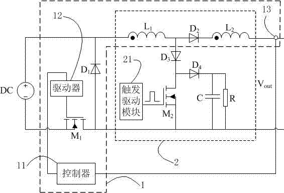
[0030] Such as figure 1 As shown, the plasma arc starting circuit of the embodiment of the present invention includes a step-down type steady current source circuit 1 and a high voltage pulse power supply circuit 2, and the step-down type steady current source circuit 1 includes a controller 11, a driver 12, and a current sampling circuit 13 , coupled inductor L with a center tap 1 and inductance L 2 , and a diode D connected between the positive and negative poles of the DC voltage source DC 1 and the first switching device, the diode D 1 The negative pole of the diode is connected to the positive pole of the DC voltage source DC, and the diode D 1 The positive pole of the first switching device is connected to one end of the first switching device, the other end of the first switching device is connected to the negative pole of the direct...


PUM


Abstract

The invention provides a plasma arc starting circuit, comprising a boost-buck type steady current source circuit (1) and a high-voltage pulse power supply circuit (2), wherein the boost-buck type steady current source circuit (1) comprises a controller (11), a current sampling circuit (13), a center-tapped coupling inductor L1 and a center-tapped coupling inductor L2, as well as a diode D1 and a first switch device connected, which are between the anode and cathodes of a DC voltage source (DC); and the high-voltage pulse power supply circuit (2) comprises a trigger drive module (21) used for transmitting pulse signals, a second switch device, an inductor L1 and an inductor L2. In order to realize the function of a plasma arc starting power supply and reduce the overall weight, the high-voltage pulse power supply is integrated with the steady current source in the invention, the dual function of a single module is accordingly realized, the problems in the switching process are avoided, and the module is simple and reliable.

Description

technical field [0001] The present invention relates to plasma arc starting circuits. Background technique [0002] Plasma has been widely used in recent years, including high-temperature plasma cutting technology, aerospace plasma propulsion technology, medical device plasma sterilization technology and so on. The power control technology of this type of plasma is an important part of the plasma generation process, and has become a technical difficulty in this industry. [0003] The traditional plasma arc starting circuit first needs to generate pulsed high voltage at the output end to plasma the gas, and then make the power supply achieve steady current output according to different work needs and application backgrounds. Therefore, the plasma arc starting circuit needs to have the dual functions of high-voltage pulse power supply and steady current source. [0004] In the existing plasma arc starting circuit, after the high-voltage pulse power supply ionizes the gas, it...

Claims


Application Information

Patent Timeline
Patent Type & Authority Applications(China)
IPC IPC(8): H02M9/02H02M3/10H05H1/48
Inventor 张东来刘贺张迪施凯敏
Owner SHENZHEN AEROSPACE NEW POWER TECH
Why Eureka
Try Eureka