A track signal filter circuit
A filter circuit and track signal technology, which is applied to electrical components, impedance networks, digital technology networks, etc., can solve the problems of being unable to suppress the influence, not having the notch function, etc., and achieve the effect of obvious suppression and simple circuit structure
Active Publication Date: 2016-08-10
ZHUZHOU CSR TIMES ELECTRIC CO LTD
View PDF0 Cites 0 Cited by
- Summary
- Abstract
- Description
- Claims
- Application Information
AI Technical Summary
Problems solved by technology
However, the disadvantage of this method is that the stopband attenuation of the designed filter circuit will not be greater than 20dB, and it does not have the notch function for the two frequency points of 50Hz and 150Hz, and cannot suppress the influence of the single-frequency signal of the power supply network on the track signal
Method used
View moreImage
Smart ImageViewing Examples
Examples
Embodiment Construction
Login to View More PUM
 Abstract
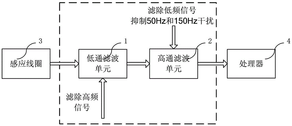
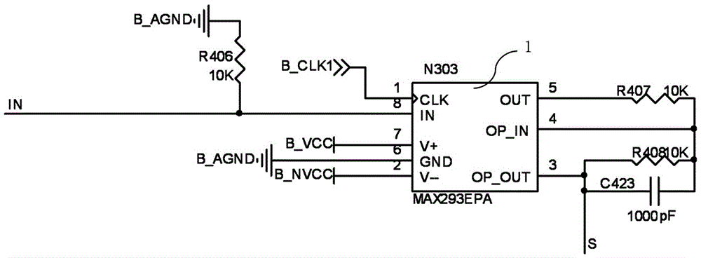
The invention discloses a track signal filtering circuit which comprises a low-pass filtering unit and a high-pass filtering unit. Band-pass filtering and trapped wave processing are carried out by a band-pass filtering circuit formed by the low-pass filtering unit and the high-pass filtering unit on voltage signals from an induction coil, and the processed voltage signals are outputted to a processor to receive signal decoding processing. The maximum passing frequency of the low-pass filtering unit is 3125Hz, and the stop-band attenuation is greater than 40dB. The minimum passing frequency of the high-pass filtering unit is 400Hz, and the stop-band attenuation is greater than 40dB. The band-pass filtering circuit formed by the low-pass filtering unit and the high-pass filtering unit has a trapped wave suppressing effect on 50Hz signals and 150Hz signals, wherein the attenuation for the 50Hz signals is greater than 80dB, and the attenuation for the 150Hz signals is greater than 60dB. The track signal filtering circuit disclosed by the invention is simple in structure, not only can filter signals outside the bandwidth, but also can suppress interferences of power supply network single-frequency signals substantially.
Description
technical field The invention relates to a filter circuit, in particular to a track signal band-pass filter circuit applied to a track traffic signal system. Background technique The track circuit is used for train occupancy detection and provides continuous operation permission information, and various track information is transmitted in the form of track signals. The train senses the rail current through the induction coil and converts it into a voltage signal. After processing the signal, it obtains the color light signal, speed level signal, etc. required for train operation, and assists the train control system to control the operation of the train. The track signal is a FSK (Frequency Shift Keying, Frequency Shift Keying) modulation waveform, which is synthesized and output by switching two sine waves of different frequencies according to a certain frequency. Different FSK modulation frequencies, that is, the switching frequencies of the two carrier frequencies repres...
Claims
Login to View More Application Information
Patent Timeline
 Patent Type & Authority Patents(China)
IPC IPC(8): H03H17/00
Inventor 罗永升代飞焦玮琦文玮陈李根袁科申竹林王业流周晓张艳
Owner ZHUZHOU CSR TIMES ELECTRIC CO LTD
Features
- R&D
- Intellectual Property
- Life Sciences
- Materials
- Tech Scout
- Unparalleled Data Quality
- Higher Quality Content
- 60% Fewer Hallucinations
Learn More Browse by: Latest US Patents, China's latest patents, Technical Efficacy Thesaurus, Application Domain, Technology Topic, Popular Technical Reports.
© 2025 PatSnap. All rights reserved.Legal|Privacy policy|Modern Slavery Act Transparency Statement|Sitemap|About US| Contact US: help@patsnap.com


