Method and device for performing degreasing treatment on steel wire

A technology of degreasing treatment and steel wire, which is applied in the electrolysis process and electrolysis components, etc., can solve the problems of difficult removal of saponified grease and poor degreasing effect of bead steel wire.

Inactive Publication Date: 2013-11-27
ZHANGJIAGANG SHENGDA STEEL ROPE
View PDF2 Cites 2 Cited by
  • Summary
  • Abstract
  • Description
  • Claims
  • Application Information

AI Technical Summary

Problems solved by technology

The disadvantage of this method is: it is difficult to remove the saponified fat remaining on the surface of the bead wire, and the degreasing effect of the bead wire is not good

Method used


Image

  • Method and device for performing degreasing treatment on steel wire
  • Method and device for performing degreasing treatment on steel wire

Examples


Embodiment 1

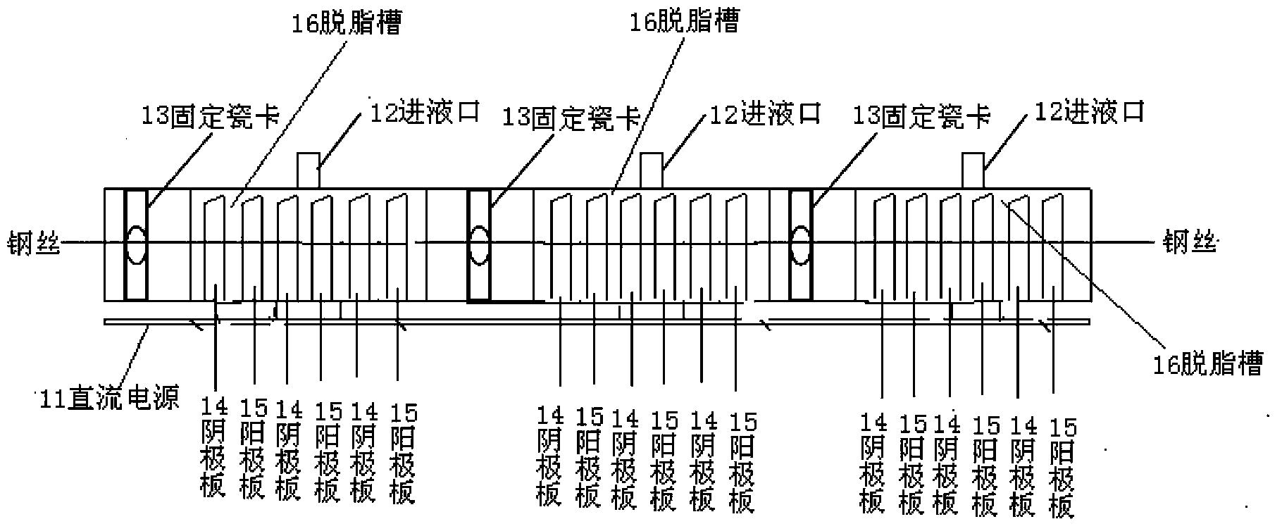
[0020] The structural diagram of a device for degreasing steel wire provided in this embodiment is as follows: figure 1 shown, including:

[0021] The degreasing tank 16 is used to contain the electrolyte, and the electrolyte has a displacement effect on the saponified fat and other grease on the surface of the steel wire passing through the electrolyte, so that the adhesion of the grease to the steel wire is reduced. The top of the degreasing tank is provided with a liquid inlet 12 through which electrolyte is poured into the degreasing tank. The main component of the above-mentioned electrolyte is sodium hydroxide, and its aqueous solution has strong conductivity. In order to prevent corrosion of the steel wire matrix, a small amount of nitrite oxidizer is also added. Therefore, the composition of the above-mentioned electrolytic solution is a large part of sodium hydroxide and a small part of nitrite oxidizing agent.

[0022] DC power supply 11, used to provide DC power ...

Embodiment 2

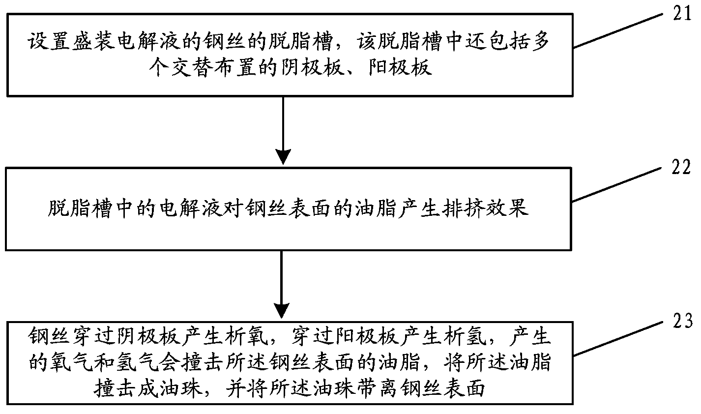
[0037] The processing flow of a method for degreasing steel wire provided by this embodiment is as follows: figure 2 As shown, the following processing steps are included:

[0038] Step 21, setting up a degreasing tank for the steel wire containing the electrolyte, and the degreasing tank also includes a plurality of alternately arranged cathode plates and anode plates.

[0039] A degreasing tank for steel wires such as bead steel wires is provided, and the degreasing tank is used to contain electrolyte. Each degreasing tank includes multiple pairs of cathode plates and anode plates, a liquid inlet, and a DC power supply. Wherein, the liquid inlet is arranged on the upper part of the degreasing tank, through which the electrolyte is poured into the degreasing tank. The DC power supply is arranged at the lower part of the degreasing tank, and the DC power supply supplies power to the electrolyte, the cathode plate and the anode plate.

[0040] The cathode plate is connected...


PUM


Abstract

The invention provides a method and a device for performing degreasing treatment on a steel wire. The method mainly comprises the following steps of: holding an electrolyte in a degreasing tank for the steel wire, supplying power to the electrolyte by using a direct-current power source, and arranging a negative plate and a positive plate in the degreasing tank, wherein when the steel wire penetrates through the hollow part of the negative plate, the negative plate causes the steel wire to have an oxidization reaction through electromagnetic induction so that oxygen is generated on the surface of the steel wire; when the steel wire penetrates through the hollow part of the positive plate, the positive plate causes the steel wire to have a reduction reaction through electromagnetic induction so that hydrogen is generated on the surface of the steel wire. The oxygen and the hydrogen are capable of hitting against grease on the surface of the steel wire so that the grease forms oil droplets and the oil droplets are removed from the surface of the steel wire. The method and the device provided by the embodiment of the invention have the advantage that the negative plate and the positive plate are arranged in the degreasing tank, so that effective degreasing treatment can be performed on steel wires such as a tire bead steel wire through electromagnetic induction between the negative plate and the steel wire and between the positive plate and the steel wire.

Description

technical field [0001] The invention relates to the technical field of degreasing treatment, in particular to a method and device for degreasing steel wire. Background technique [0002] In the daily production process of bead wire, a large amount of saponified fat and other oils will remain on the surface of the steel wire after drawing. This kind of saponified fat has a very low solubility in water and cannot be completely removed. These saponified fats will have a great impact on the subsequent copper plating process of the bead wire, resulting in problems such as poor surface quality of the bead wire coating and reduced rubber adhesion. [0003] A method for degreasing the bead wire in the prior art is: cleaning the bead wire with a single acid solution. The disadvantage of this method is: it is difficult to remove the saponified fat remaining on the surface of the bead wire, and the degreasing effect of the bead wire is not good. Contents of the invention [0004] E...

Claims


Application Information

Patent Timeline
Patent Type & Authority Applications(China)
IPC IPC(8): C25F1/04C25F7/00
Inventor 陆海徐一铭徐丹
Owner ZHANGJIAGANG SHENGDA STEEL ROPE
Why Eureka
Try Eureka