The supporting device and driving circuit of cascaded electron beam diode suspension electrodes

A suspension electrode and support device technology, applied in the installation/support/configuration/insulation of electrode components, X-ray tube electrodes, X-ray tube components, etc., can solve problems such as insufficient insulation performance and the influence of electric field distribution, and achieve The movement speed is fast, the suspension work is guaranteed, and the effect of overcoming the insufficient insulation performance

Inactive Publication Date: 2015-10-28
NORTHWEST INST OF NUCLEAR TECH
View PDF4 Cites 0 Cited by
  • Summary
  • Abstract
  • Description
  • Claims
  • Application Information

AI Technical Summary

Problems solved by technology

[0006] Aiming at the problem that the suspension electrode support structure existing in the diode cascade has insufficient insulation performance under the action of high voltage and has an impact on the electric field distribution, a cascaded electron beam diode suspension electrode based on a movable support structure is proposed. The support device and its driving circuit, at the moment before the diode works, the support pin is removed by external force, the suspended electrode falls freely under the action of gravity, and the inertia of the object is used to realize the suspension of the middle electrode, realizing the instantaneous multi-gap diode cascade Work

Method used


Image

  • The supporting device and driving circuit of cascaded electron beam diode suspension electrodes
  • The supporting device and driving circuit of cascaded electron beam diode suspension electrodes
  • The supporting device and driving circuit of cascaded electron beam diode suspension electrodes

Examples


Embodiment Construction

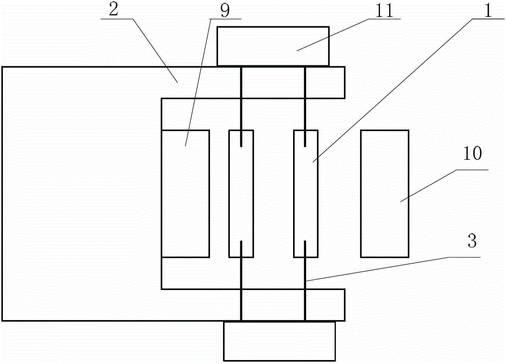
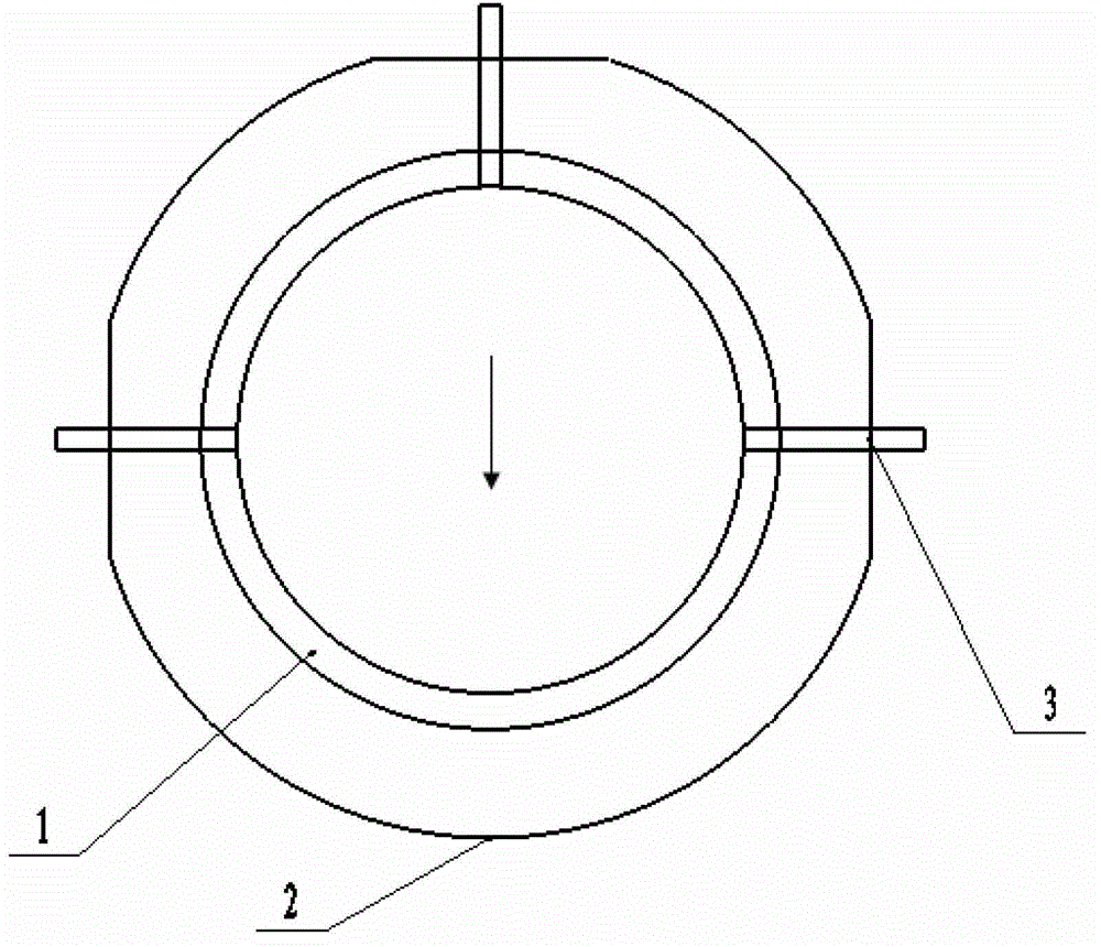
[0028] figure 1 It is a schematic diagram of the structural position of the supporting device and the cascaded diode of the present invention. There is not less than one floating electrode 1 arranged at a coaxial interval between the cathode 9 and the anode 10 of the conventional electron beam diode. The floating electrode 1 is usually a ring-shaped flat plate , the working surface is parallel to the working surface of the diode anode 10 and the diode cathode 9, and the centers of the suspension electrode 1, the diode anode 10 and the diode cathode 9 are in a straight line; the suspension electrode 1 is supported by several supports fixed on the housing of the electron beam diode Supported by the unit 11, the housing 4 of the supporting unit 11 is fixed on the housing 2 of the electron beam diode. Through the support and withdrawal of the supporting pin 3, the instantaneous suspension operation of multiple groups of high-voltage floating electrodes 1 is realized.

[0029] The ...


PUM


Abstract

The invention relates to a supporting device for a cascade connection type electron beam diode suspension electrode and a driving circuit of the supporting device for the cascade connection type electron beam diode suspension electrode. The supporting device for the cascade connection type electron beam diode suspension electrode comprises three supporting units, wherein each supporting unit comprises a supporting pin, a shell body, a spring, an iron core and an electromagnetic coil, wherein each electromagnetic coil is installed outside the tube wall of each shell body, each spring is installed inside each shell body, each iron core is arranged at the front end of each spring, a through hole is formed in the center of each iron core, each iron core and each supporting pin are fixedly connected into a whole, and each supporting pin can move back and forth through electromagnetic force generated by each electromagnetic coil and through each spring, so that the cascade connection type electron beam diode suspension electrode is fixed and is released. Due to the fact that the supporting device for the cascade connection type electron beam diode suspension electrode and the driving circuit of the supporting device for the cascade connection type electron beam diode suspension electrode achieve suspension operation of the high-voltage electrode, the defect that a fixing support is not good enough in insulating performance under the action of high voltage, and has influence on distribution of electric fields is overcome.

Description

technical field [0001] The invention relates to the technical field of pulse power, in particular to a supporting device and a driving circuit of an electron beam cascaded diode floating electrode with multi-gap cascade operation. Background technique [0002] To carry out the research on the electromagnetic pulse effect of the system, it is necessary to establish a hard X-ray source with a high-energy fluence and an energy spectrum distribution between 20 and 120keV. The energy spectrum of the hard X-ray depends on the energy of the bremsstrahlung electron beam. Two or more stages of partial pressure reduce the energy of the electron beam, which can produce hard X-rays with large area, realistic energy spectrum and high energy fluence. Double Eagle in the United States has carried out two-stage and three-stage cascaded diodes and obtained good experimental data. [0003] In pulsed power technology, a vacuum diode acts as a load for a transmission line, and its function is ...

Claims


Application Information

Patent Timeline
Patent Type & Authority Patents(China)
IPC IPC(8): H01J1/88H01J35/04
Inventor 杨莉来定国任书庆张玉英杨实姚伟博程亮张永民
Owner NORTHWEST INST OF NUCLEAR TECH
Why Eureka
Try Eureka