0-dB directional coupler based on multilayer technology

A directional coupler and technology, which is applied in the direction of waveguide-type devices, circuits, connecting devices, etc., can solve the problems of difficult to meet the requirements of miniaturization of electronic equipment and high degree of orientation, and achieves avoiding processing difficulties, compact system equipment, and improving circuit. The effect of stability

Inactive Publication Date: 2013-11-27
UNIV OF ELECTRONICS SCI & TECH OF CHINA
View PDF4 Cites 10 Cited by
  • Summary
  • Abstract
  • Description
  • Claims
  • Application Information

AI Technical Summary

Problems solved by technology

Therefore, although the forward coupler can achieve 0-dB coupling and has a high degree of orientation, it is difficult to meet the needs of today's electronic equipment miniaturization

Method used


Image

  • 0-dB directional coupler based on multilayer technology
  • 0-dB directional coupler based on multilayer technology
  • 0-dB directional coupler based on multilayer technology

Examples


Embodiment Construction

[0024] The present invention will be further described below in conjunction with the accompanying drawings and specific embodiments.

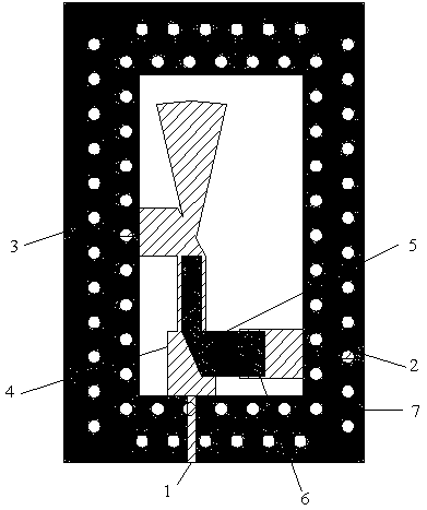
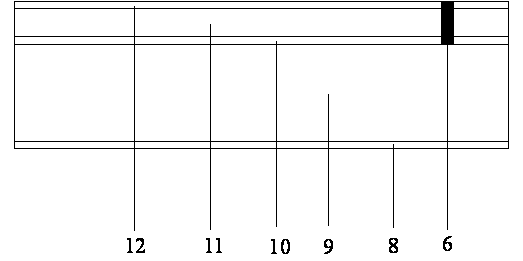
[0025] combine figure 1 , figure 2 As shown, it is realized in a three-dimensional structure based on LTCC multilayer technology, with a total of 5 layers, including 2 dielectric layers and 3 metal layers. The two ends of the upper coupled line are coupled ports and straight-through ports respectively. At the same time, a quarter-wavelength fan-shaped open-circuit stub is loaded on the side of the straight port at the end of the upper coupled line. One end of the lower coupled line is connected to the coupled port through the interconnection hole 6, and The other end is an open circuit, and the upper and lower layer coupling lines form broadside coupling. The bottom layer is a metal ground plate 8 , the second layer is a dielectric substrate 9 , and the third layer is a metal layer 10 .

[0026] The two ends of the coupling line 4 on the u...


PUM


Abstract

The invention discloses a 0-dB directional coupler based on a multilayer technology, and relates to the technical field of microwaves. The directional coupler is a three-port device with a first port, a second port and a third port. One end of an upper-layer coupling line is connected with the first port to form a first coupling port, the other end of the upper-layer coupling line is connected with the third port to form a straight-through port, a quarter wavelength open circuit branch knot is loaded to the straight-through port, one end of a lower-layer coupling line is connected with the second port through a connecting hole to form a second coupling port, and the other end of the lower-layer coupling line is in an open circuit mode. The 0-dB directional coupler based on the multilayer technology is achieved through a multi-layer three-dimensional structure in a broad-brimmed coupling mode, effectively reduces the size of a circuit, reduces processing difficulties caused by tight coupling, improves circuit stability, simplifies the circuit structure, can be applied to sub-harmonic mixer signal feed-in networks and other functional circuit modules in a radio frequency communication system and achieves high-strength isolation between signals.

Description

technical field [0001] The invention relates to the technical field of wireless communication, in particular to a 0-dB directional coupler based on multilayer technology. Background technique [0002] Directional coupler is a microwave and millimeter wave multi-port component with directional transmission characteristics. It is widely used in microwave systems and can be used for signal isolation, separation and mixing, such as power detection, signal source isolation, frequency sweep test of transmission and reflection. Wait. [0003] The directional coupler is composed of two transmission lines, and the coaxial line, rectangular waveguide, strip line and microstrip line can realize the directional coupler. Therefore, from the structural point of view, there are many kinds of directional couplers with great differences. From the perspective of coupling mechanism, it can be divided into two types: forward type and backward type. The forward type works based on the differen...

Claims


Application Information

Patent Timeline
Patent Type & Authority Applications(China)
IPC IPC(8): H01P5/18
Inventor 李家林张博王心洋绍维王秉中
Owner UNIV OF ELECTRONICS SCI & TECH OF CHINA
Why Eureka
Try Eureka