Neutral point potential balance control method for direct current side in NPC three-level structure
A potential balance and control method technology, which is applied in the direction of converting AC power input to DC power output, photovoltaic power generation, electrical components, etc., can solve the problems of midpoint potential imbalance, adverse performance and safety of inverters, and inaccurate calculation of zero-sequence voltage. Accurate and other issues, to achieve the elimination of DC bias and low frequency fluctuations, the control algorithm is simple and easy, and the effect of improving the quality of output current
- Summary
- Abstract
- Description
- Claims
- Application Information
AI Technical Summary
Problems solved by technology
Method used
Image

Examples
Embodiment
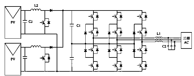
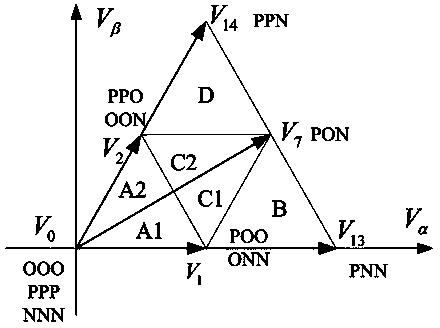
[0038] see figure 1 , After connecting the photovoltaic inverter, the control chip will obtain the three-phase inductor current through the sampling circuit , , , and the small vector that can affect the midpoint potential is obtained by calculation , and medium vector The action time is , and , the currents corresponding to the midpoint when they act are respectively , and . You can do the following, see image 3 :
[0039] like , the reference voltage is located in the small triangle 1 of the first sector:
[0040] (1) If , select As a redundant small vector for regulation, according to the required current at the midpoint , calculate the distribution coefficient of the redundant small vector ;
[0041] (2) If , select As a redundant small vector for regulation, according to the required current at the midpoint , calculate the distribution coefficient of the redundant small vector .
[0042] like , the reference voltage is locat...
PUM
 Abstract
Description
Claims
Application Information