
Random noise correction method and device

A random noise and correction method technology, applied in the field of image processing, can solve the problems of large statistical errors and large system errors

Inactive Publication Date: 2013-12-04
NEUSOFT MEDICAL SYST CO LTD
View PDF4 Cites 12 Cited by
  • Summary
  • Abstract
  • Description
  • Claims
  • Application Information

AI Technical Summary

Problems solved by technology

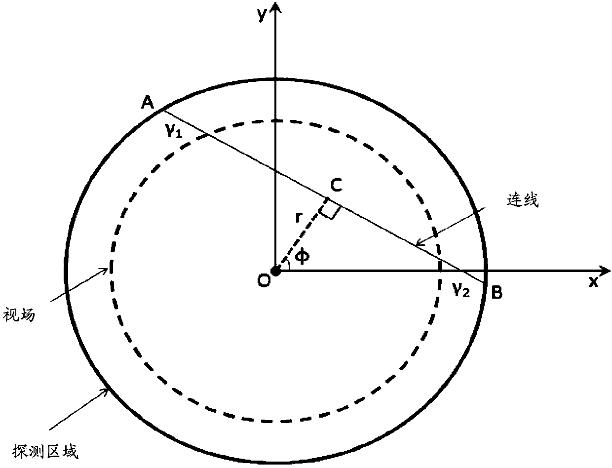
[0012] When using the single photon counting rate method to obtain random chord diagrams, because the detector has a relatively high single counting rate, the statistical error is relatively small. The error is large; when the delayed coincidence window method is used to obtain random chord diagrams, the factors affecting the coincidence time, detection efficiency, and coincidence loss of immediate coincidence and delayed coincidence are the same, and the system has little influence, but the delayed chord diagram obeys an independent Poisson distribution. have a large statistical error

Method used


Image

  • Random noise correction method and device
  • Random noise correction method and device
  • Random noise correction method and device

Examples


Embodiment 1

[0145] Figure 4 It is a flow chart of Embodiment 1 of a method for correcting random noise in the present invention, and the method includes:

[0146] Step 401: collecting the scan data of the detector to obtain the instant chord diagram, delayed chord diagram and single photon count rate.

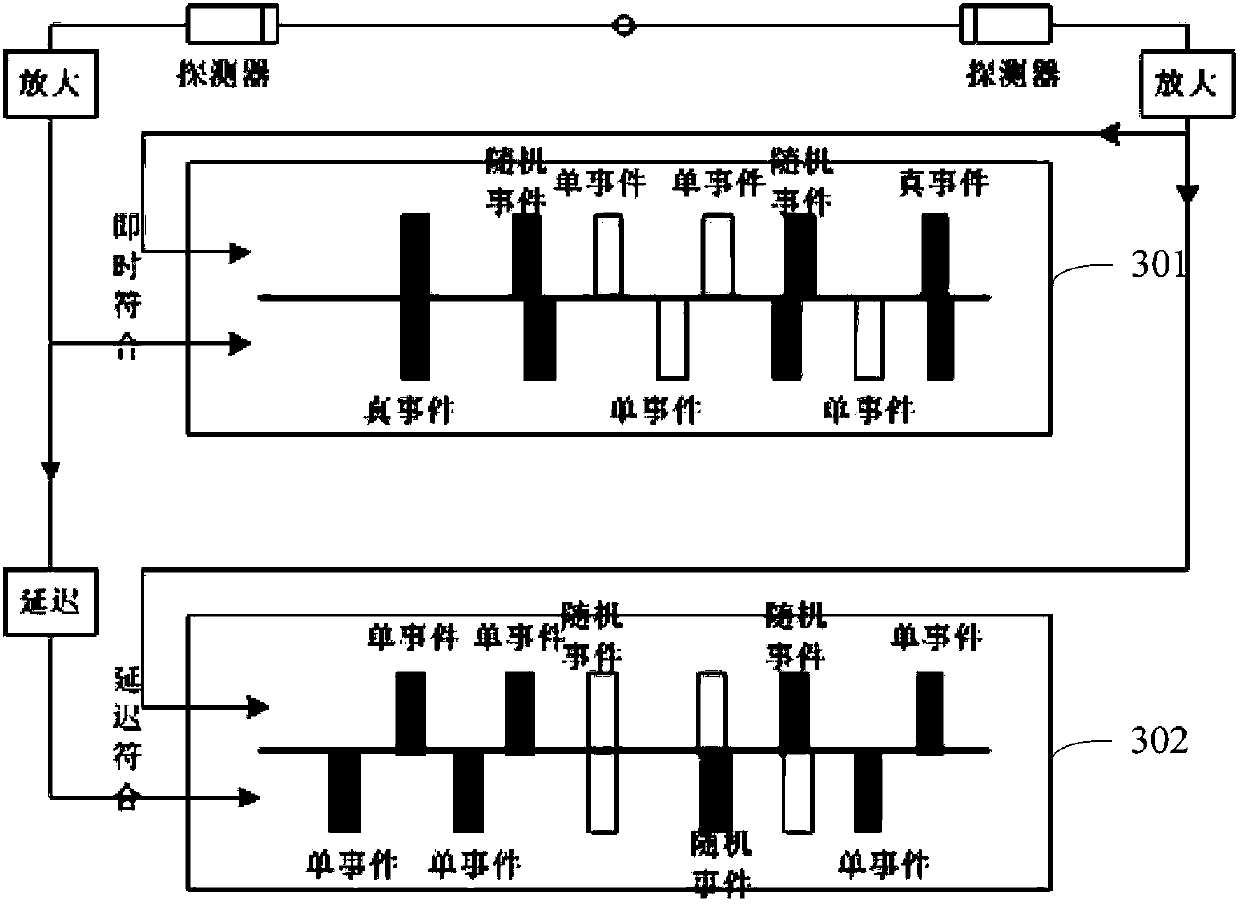
[0147] The two event sequences received by the two detectors are arranged in two columns in chronological order, as shown in Figure 301, and the two event sequences are matched to obtain an instant chord diagram. In the instant chord diagram, the event produced by two detectors receiving two photons produced by the same positron annihilation in the same time window is a real event. The event produced by two detectors receiving different photons generated by positron annihilation in the same time window is a random event, and the random event is the noise in the real-time chord diagram.

[0148] The two detectors record the two sequences of events received, and delay one of the sequence ...

Embodiment 2

[0176] Figure 5 It is a flow chart of Embodiment 2 of a random noise correction method of the present invention. Compared with Embodiment 1, Embodiment 2 obtains a compressed random chord graph according to the compressed position of the compressed real-time chord graph, and uses the compressed random chord graph to correct the compressed real-time chord graph , the method includes:

[0177] Step 501: collecting the scan data of the detector to obtain the delay chord diagram and the single photon count rate, and compressing the scan data to obtain the compressed instant chord diagram.

[0178] Here, it is similar to Embodiment 1, and reference is made to the description of Embodiment 1, and details are not repeated here.

[0179] Step 502: Obtain a distribution chord diagram according to the single photon count rate.

[0180] The obtaining the distribution chord diagram according to the single photon count rate comprises:

[0181] Obtaining a count rate chord diagram accor...

Embodiment 3

[0192] Figure 6 It is a flow chart of Embodiment 3 of a random noise correction method of the present invention. Compared with Embodiment 1, Embodiment 3 compresses the delayed chord diagram and the single photon counting rate according to the compressed position of the collected compressed instant chord diagram to obtain the compression Delaying the chord diagram and compressing the single photon count rate, using the compressed chord diagram to correct the compressed instant chord diagram, the method includes:

[0193] Step 601: collecting the scan data of the detector to obtain the delayed chord diagram and the single photon count rate, and compressing the scanned chord diagram to obtain the compressed instant chord diagram.

[0194] Here, it is similar to Embodiment 1, and reference is made to the description of Embodiment 1, and details are not repeated here.

[0195] Step 602: Obtain the compressed position of the compressed instant chord diagram.

[0196] Step 603: C...


PUM


Abstract

The invention provides a random noise correction method and device. The method includes the steps of collecting scanning data of a detector to obtain an immediate chordal graph, a delay chordal graph and a single photon counting rate, obtaining a distribution chordal graph according to the single photon counting rate, distributing data sum of the delay chordal graph to the distribution chordal graph to obtain a random chordal graph, and utilizing the random chordal graph to correct the immediate chordal graph to obtain a correction chordal graph. The random chordal graph is generated by the distribution chordal graph obtained through the delay chordal graph and the single photon counting rate, the delay chordal graph is small in system error, the distribution chordal graph is small in statistical error, and therefore the random chordal graph obtained through the delay chordal graph and the distribution chordal graph is small in system error and statistical error and the correction chordal obtained through correction of the immediate chordal graph through the random chordal graph is small in system error and statistical error.

Description

technical field [0001] The invention relates to the technical field of image processing, in particular to a random noise correction method and device. Background technique [0002] Positron Emission Computed Tomography (PET) technology is to label substances necessary for biological life metabolism, such as glucose, protein, nucleic acid, fatty acid, with short-lived radionuclides (such as F18, C11, etc.), by detecting the accumulation position of radionuclides in the metabolism of biological life, it can reflect the situation of life metabolic activities, so as to achieve the purpose of diagnosis. [0003] Due to the relatively short lifetime of the radionuclide, positrons are released during the decay process, and a positron encounters an electron after traveling a few tenths of millimeters to a few millimeters and then annihilates, thereby generating energy in the opposite direction (180 degrees) A pair of photons (based on pair production) at 511KeV. Therefore, PET equ...

Claims


Application Information

Patent Timeline
IPC IPC(8): A61B6/03
Inventor 刘勺连常杰李明
Owner NEUSOFT MEDICAL SYST CO LTD
Learn More