
Plunger

A technology of shells and blanks, applied in the directions of fuel injection pumps, mechanical equipment, valve devices, etc., can solve problems such as structural space limitation conflicts, and achieve the effects of simple manufacturability, compact structure, and high load

Inactive Publication Date: 2013-12-04
SCHAEFFLER TECH AG & CO KG
View PDF6 Cites 9 Cited by
  • Summary
  • Abstract
  • Description
  • Claims
  • Application Information

AI Technical Summary

Problems solved by technology

Increasing demands on the load-carrying capacity of the tappets, e.g. due to increased rotational speeds and increased injection pressures, require a more robust design, which however conflicts with installation space constraints

Method used


Image

  • Plunger

Examples


Embodiment Construction

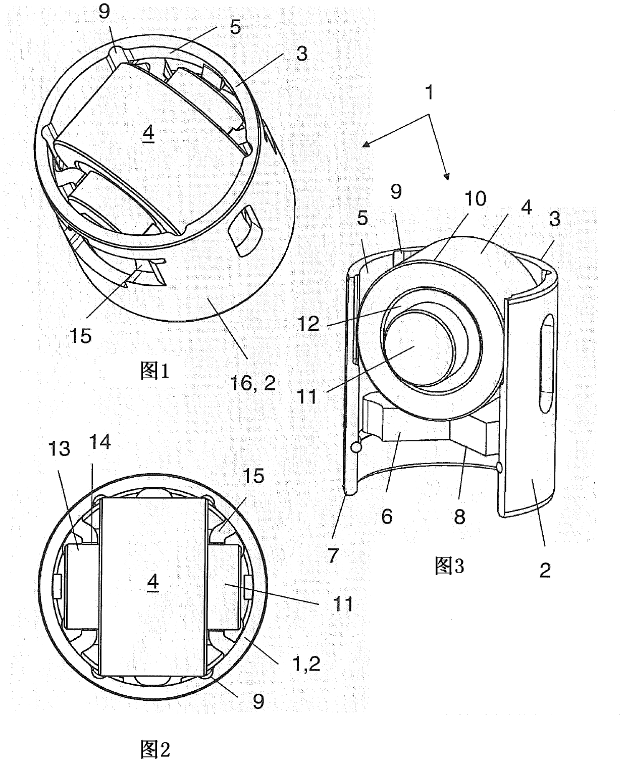
[0016] A tappet 1 of a high-pressure pump for diesel fuel of an internal combustion engine is shown here. The tappet 1 has a cylindrical housing 2 which, in the region of the upper first annular end 3 , accommodates the majority of the roller 4 for striking the travel cam within its inner circumference 5 .

[0017] Axially below the rollers 4 , a separate bridge 6 passes through the deep-drawn housing 2 from a steel sheet. The bridge is present as a separate stamped plate, whose bottom side 8 facing the lower second ring end 7 of the housing 2 serves as abutment for the pump piston as tappet follower.

[0018] In the direction of the first ring end 3 , the bridge 6 is supported on the secant joists of the diametrically opposite setback region 15 of the housing 2 .

[0019] As shown outside, the rollers 4 run via roller bearings 12 on pins 11 . The pins 11 are accommodated with their ends 13 in part-cylindrical receptacles 14 of the respective indented regions 15 of the housi...


PUM


Abstract

Provided is a plunger (1) particularly used for a fuel injection pump. The pluger has a housing (2) receiving a roller (4) used for being struck by a cam, wherein the roller is in a cylindrical inner circumference side (5) in a region of a first annular end (3), a bridge piece (6) axially projects through the housing (2) below the roller (4), and a bottom side (8) of the bridge piece faces towards a second annular end (7) of the housing, and functions as a system for a plunger follower. Four notch-like discharges (9) extend along the inner circumference side (5) of the housing (2), and the roller (4) with ring edges (10) projects into the discharges.

Description

technical field [0001] The invention relates to a tappet, in particular for a pump or a compressor, having a housing with a substantially cylindrical inner circumference, at least in this section, in the region of a first annular end head. The side interior accommodates the rollers for striking the periodic stroke generator, wherein, axially below the rollers, a bridge passes through the housing, the second annular end of the bridge facing the housing At least indirectly, the bottom side serves as abutment for the tappet follower. Background technique [0002] Such a tappet is already known from DE 10 2010 022 318 A1. It is used in highly loaded fuel injection pumps of internal combustion engines. The ever-increasing demands on the load-bearing capacity of the tappets, for example caused by increased rotational speeds and increased injection pressures, require a more robust design, which however conflicts with installation space constraints. It can therefore be appreciate...

Claims


Application Information

Patent Timeline
Patent Type & Authority Applications(China)
IPC IPC(8): F04B9/04F01L1/18F02M59/10
CPCF01L2103/00F01L1/146F04B1/0426F02M2200/8053F04B9/04F01L2105/00F02M59/102F04B1/0408F01L2107/00F01L1/18F02M59/10F01L2303/00F01L2305/00F01L2307/00
Inventor 斯特凡·多恩诺伯特·盖耶
Owner SCHAEFFLER TECH AG & CO KG
Learn More