Light emitting diode detection measuring tool

A technology for light-emitting diodes and measuring tools, applied in the field of general-purpose measuring tools, can solve the problems of loss of reproducibility of light-emitting diode light sources 203, large differences in luminous flux values, and lack of applicability, so as to improve long-term reliability, improve detection quality, and simplify manufacturing processes. Effect

Inactive Publication Date: 2013-12-04
CHAMP TECH OPTICAL FOSHAN +1
View PDF0 Cites 6 Cited by
  • Summary
  • Abstract
  • Description
  • Claims
  • Application Information

AI Technical Summary

Problems solved by technology

After long-term experiments and careful verification, the creators have confirmed that the luminous flux data in the initial stage of the transient state are more than double the long-term stable steady-state luminous flux data under the test conditions that will not cause damage to the light-emitting diode light source 203. The luminous flux values ​​measured at different initial moments are very different, and the reproducibility of detecting the same LED light source 203 is lost, so that only the manufacturer of the LED light source 203 vigorously advocates and provides terminal users with such transient initial data, but The actual lamp performance of the LED lighting industry is of reference value only under long-term steady-state operation, and the exaggerated data at the initial stage of the transient state provided by the manufacturer has no practical significance at all.
In the measurement method specification (CIE 127:2007, Measurement of LEDs) of the world's authoritative light-emitting diode light source 203, the measurement method for the above-mentioned initial transient state must only be available under a clear correlation between the transient state and the steady state. Conceptual description, but because the correlation will vary with LED products of different manufacturers, it is completely impossible to standardize for the majority of lighting application end users, so that it lacks practical applicability; therefore, the LED light source 203 The detection is still based on the long-term steady-state data that is consistent with the actual application and reproducible

Method used


Image

  • Light emitting diode detection measuring tool
  • Light emitting diode detection measuring tool
  • Light emitting diode detection measuring tool

Examples


Embodiment Construction

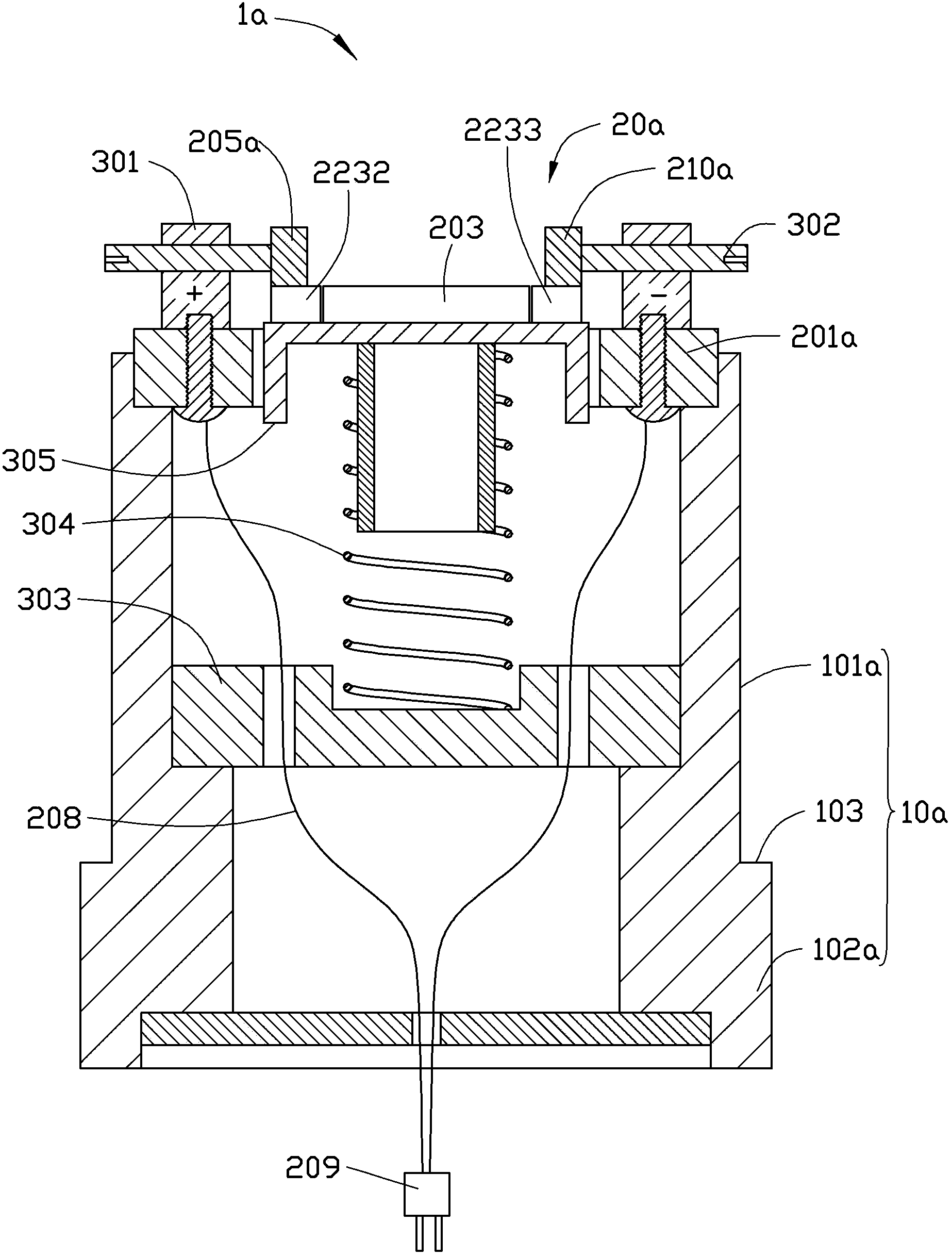
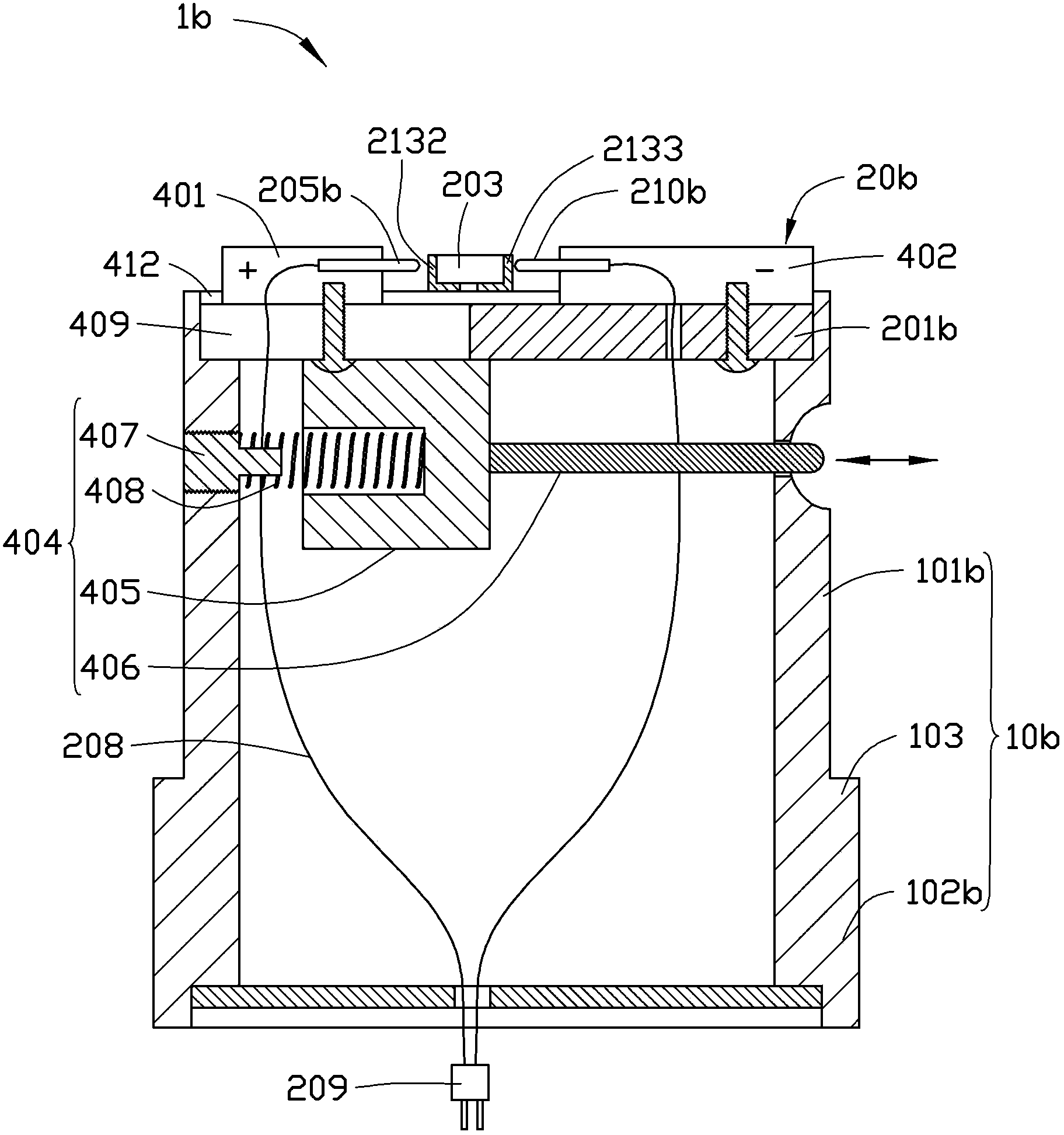
[0078] Refer to the following Figure 4 Turning to FIG. 9 , the universal measuring tool for detecting light-emitting diodes of the present invention is further described.

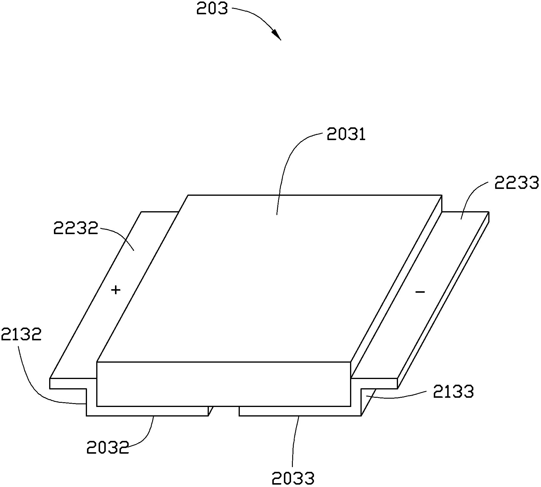
[0079] Figure 4 It is a schematic cross-sectional view of the assembly of the first embodiment of the present invention, Figure 5A and Figure 5B respectively Figure 4 The top and bottom perspective views of the test department in the center, Figure 6 for Figure 4 Schematic diagrams of the two telescopic assemblies in Figure 7A and Figure 7B respectively Figure 4 The schematic diagram of the two kinds of electrodes;

[0080] The shell portion 10 is a hollow cylinder with an opening at least towards one end to install the test portion 20. The outer peripheral wall of the cylinder extends axially from the opening to form a thinner front section 101 and is formed between the remaining thicker rear section 102 walls. Right-angled step surface 103; the outer peripheral wall surface size of the ...


PUM


Abstract

A measuring tool generally used for detecting an LED light source comprises a shell part and a testing part. The shell part is a hollow cylinder, and at least one end of the shell part is opened to contain the testing part. The testing part comprises a carrier plate and a fin, wherein the carrier plate is arranged on the opening end portion, and the fin extends on the inner side, towards the shell part, of the carrier plate. At least one air hole penetrating through the carrier plate is formed in the middle of the carrier plate, and the air hole is communicated with a vacuum pump outside the shell part. Any two opposite angle sides, close to the air hole, of the end face of the outer side of the carrier plate are provided with at least a pair of electrodes which are communicated with an external control power source and are used for guiding positive voltage and negative voltage. An annular refrigeration chip surrounding the electrodes and the air hole is embedded into the outer side of the carrier plate to enable an LED to be tested at the constant temperature. A fan for guiding cooling blast to the fin is arranged at the bottom of the shell part, and when the middle, away from the light-emitting face, of the LED to be tested abuts against the air hole, the LED can be attached to the carrier plate through attraction provided by the vacuum pump, and an electrode plate at the bottom of the LED is correspondingly connected with the electrodes to supply electricity to the LED.

Description

technical field [0001] The invention relates to a light-emitting diode detection measuring tool, in particular to a light-emitting diode attached to the area to be tested through suction, which can provide a constant temperature environment during detection, has the advantages of not blocking light, easy operation, high accuracy, and is suitable for different It is a universal measuring tool applicable to the size, shape, structure and type of light-emitting diodes. Background technique [0002] The light and power measurement system for detecting light-emitting diodes (LED, Light Emitting Diode) is to install the measuring tool carrying the light source of the light-emitting diode into the integrating sphere, and connect the surrounding spectrum analyzer, electrical parameter measuring instrument and light-emitting diode to control the power supply to achieve The function of detecting parameters such as chromaticity coordinates, color temperature, color rendering index, col...

Claims


Application Information

Patent Timeline
Patent Type & Authority Applications(China)
IPC IPC(8): G01J1/02G01R1/02G01R31/44
CPCG01R31/2635G01J1/0252G01R31/44G01J2001/4252G01J1/0223
Inventor 刘泰健
Owner CHAMP TECH OPTICAL FOSHAN
Why Eureka
Try Eureka