
Early determination method for substation grounding grid

A technology for substation grounding grid and determination method, which is applied in the field of early determination of substation grounding grid structure, can solve problems such as errors and inability to accurately calculate the engineering quantity of the grounding grid, and achieve the effect of strong engineering practicability and economical efficiency

Inactive Publication Date: 2013-12-04
STATE GRID CORP OF CHINA +1
View PDF1 Cites 12 Cited by
  • Summary
  • Abstract
  • Description
  • Claims
  • Application Information

AI Technical Summary

Problems solved by technology

Generally, in the stage of engineering feasibility study and preliminary design, the designer only needs to provide the substation soil resistivity and corrosion conditions, the selection of grounding materials, the technical principles of grounding device design, the calculation results of contact potential and step potential, and the required resistance reduction measures. , anti-corrosion, isolation measures, etc., without the need to draw the substation grounding protection plan layout, which resulted in the inability to accurately calculate the engineering quantity of the grounding grid in the feasibility study and initial design stages
However, when estimating and budgeting, the designer is required to provide the technical and economic personnel with a bill of quantities for the grounding grid
Faced with this situation, in the actual engineering design process, designers often roughly estimate the engineering quantity of the grounding grid based on the construction scale of the substation, relying on design experience and referring to projects that have been completed and put into operation. This approach often brings large errors

Method used


Image

  • Early determination method for substation grounding grid
  • Early determination method for substation grounding grid
  • Early determination method for substation grounding grid

Examples


Embodiment Construction

[0062]The following examples of the present invention will be further described in detail. The following examples are only descriptive, not restrictive, and cannot limit the protection scope of the present invention.

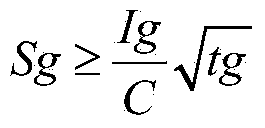
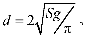
[0063] An early determination method for a substation grounding grid structure, the method steps are as follows:

[0064] The first step is to obtain the total fault current and shunt coefficient of the grounding network, and calculate the short-circuit current into the ground;

[0065] ⑴ Use two formulas to calculate the short-circuit current into the ground respectively: use the obtained total fault current and shunt coefficient of the grounding grid to calculate the short-circuit current into the ground of the substation through the grounding device, and when a grounding short-circuit occurs inside or outside the substation, the The current is calculated according to the following two formulas:

[0066] I=(I max -I n )(1-K e1 ) (a)

[0067] I=I n (1-K ...


PUM


Abstract

The invention relates to an early determination method for a substation grounding grid. The method includes the steps: acquiring total fault current and current divider coefficient of the grounding grid and calculating buried short-circuit current; acquiring the size of a station zone of a substation and calculating the total area of the station zone; calculating the minimum section of a grounding body and selecting the shape and the section of the grounding body; calculating and checking the grounding resistance of the grounding body; calculating and checking maximum contact potential and step voltage of the station zone; performing economic and technical comparison on the grounding body meeting requirements to determine the optimal grounding grid design scheme; generating a grounding grid design calculation sheet, an engineering quantity list and an estimation sheet or approximate estimation sheet. The optimal grounding grid design scheme can be early determined, the method effectively solves the problem that a detailed engineering structure and use materials cannot be accurately determined at researchable and preliminary design stages, and an early design method is provided for the substation grounding grid engineering.

Description

technical field [0001] The invention belongs to the technical field of substation design in electric power systems, in particular to an early determination method for a substation grounding grid structure. Background technique [0002] For the needs of work and safety, some conductive parts of the electrical installations and facilities in the power system or buildings are connected to the ground electrode through the ground wire, which is grounding. Grounding resistance is one of the important technical indicators to characterize the electrical performance of the grounding device. It refers to the ratio of the voltage U on the electrode to the current I when the current I flows into the earth through the grounding electrode. It includes the resistance of the grounding lead wire and the resistance of the grounding electrode body. , the contact resistance between the ground electrode and the soil and the soil resistance from the electrode to infinity. [0003] Since the grou...

Claims


Application Information

Patent Timeline
Patent Type & Authority Applications(China)
IPC IPC(8): H02B5/01
Inventor 王楠梁伟毛华李盛伟程雅楠王兆峰冯殿珍马力耿芳
Owner STATE GRID CORP OF CHINA
Learn More