Metering unit

A technology for measuring components and liquid flow, applied in the direction of flow control, special packaging objects, non-electric variable control, etc., can solve the problems of unreliability, large amount of bacteria in food, inaccurate measurement, etc., and achieve the effect of compact design

Active Publication Date: 2013-12-04
BURKERT WERKE
View PDF5 Cites 2 Cited by
  • Summary
  • Abstract
  • Description
  • Claims
  • Application Information

AI Technical Summary

Problems solved by technology

[0005] This gas component can adversely affect the flow measurement of the liquid so that the metering will then become imprecise and unreliable
However, especially in the food industry, a very precise dosing process is necessary, since o

Method used


Image

  • Metering unit
  • Metering unit
  • Metering unit

Examples


Embodiment Construction

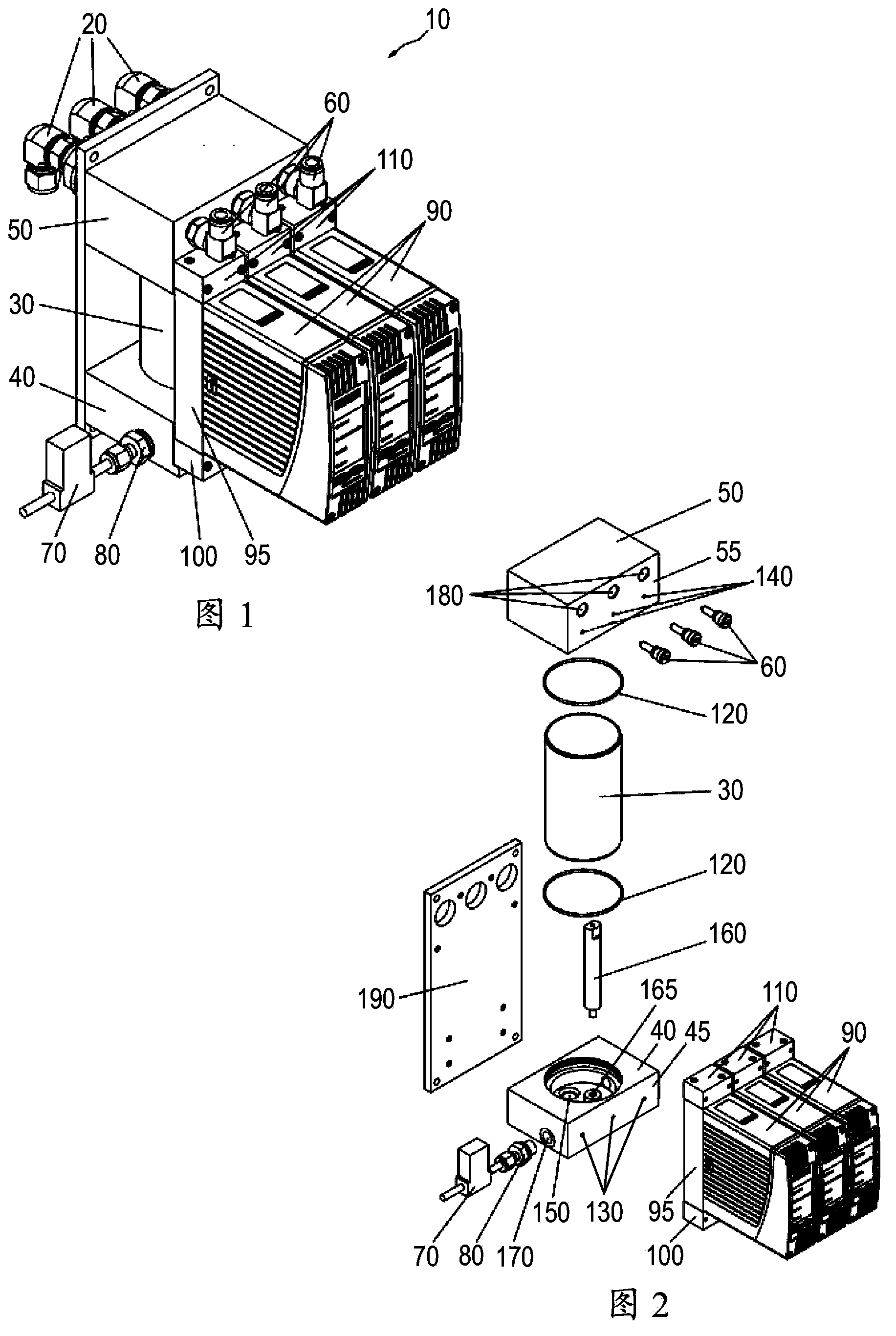
[0034] figure 1 It is shown that the metering assembly 10 for preparing aerosols has three outlets 20. A common buffer container 30 for receiving liquid is arranged between the first carrier module 40 at the bottom and the second carrier module 50 at the top, the liquid being a component of the aerosol to be metered.

[0035] The two carrier modules 40, 50 are generally rectangular monolithic parts shaped so as to be parallel to each other.

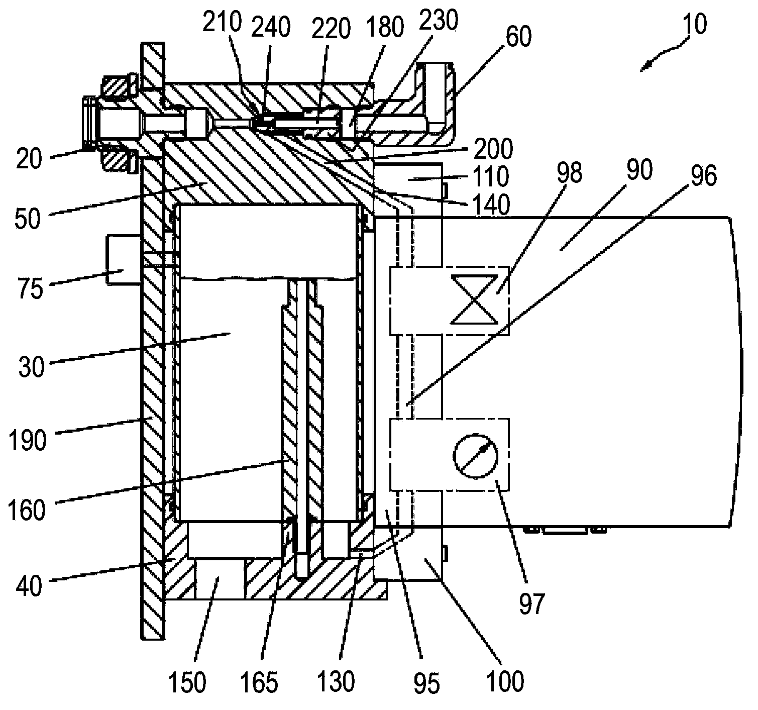
[0036] The carrier gas is supplied via the connector 60 on the carrier module 50, and the liquid for forming aerosol is mixed into the carrier gas (in image 3 Detailed in).

[0037] The first carrying module 40 has a port 80, and a pressure reducing valve 70 for controlling the pressure in the buffer container 30 is connected to the port 80.

[0038] The three liquid flow controllers 90, each formed as a structural component, each have a fluid block 95, and the three liquid flow controllers 90 are fixed to one end 100 of the fluid block 95 by me...


PUM


Abstract

In a metering unit (10) having at least one outlet (20) for dispensing an aerosol with a defined concentration, with at least one inlet (180) for a carrier gas, at least one inlet for a liquid, preferably for a hydrogen peroxide solution, and a buffer container (30) for the liquid, it is provided that the metering unit (10) has at least one liquid flow controller (90) on the outflow side.

Description

Technical field [0001] The present invention relates to a metering assembly for preparing an aerosol, which preferably contains a hydrogen peroxide solution as a liquid component. Background technique [0002] Such aerosols are used in the food industry, for example for sterilization and packaging. [0003] In a metering device for preparing an aerosol with a prescribed liquid concentration, the flow rate of the liquid is often measured and the opening time of the on-off valve is adapted to the determined flow value. [0004] The 35% hydrogen peroxide solution usually used for disinfection purposes is easily at least partially decomposed into oxygen and water (especially at such high concentrations) in order to leave the liquid phase, and there will always be a gas phase. [0005] This gas component can adversely affect the flow measurement of the liquid, so that the measurement will subsequently become inaccurate and unreliable. However, especially in the food industry, a very preci...

Claims


Application Information

Patent Timeline
IPC IPC(8): G05D7/06B05B12/00B65B55/10B65D83/54
CPCB65B31/003G05D7/0635B65B55/10B65D83/54B67C3/001B05B7/2494B67D7/78B67C7/0073B05B7/005B67C7/008B67C3/005B67C7/0086B05B7/062B05B7/0416B01F25/30B01F25/312B01F25/313
Inventor 安德鲁斯·多尔马丁·智利安德鲁斯·格劳约翰·格尼斯克里斯汀·克莱恩伯格哈罗德·沙费尔
Owner BURKERT WERKE
Why Eureka
Try Eureka