
Novel combined filtering unit

A filter device and a new type of technology, applied in the direction of filter screen, solid separation, grid, etc., can solve the problems of separating minerals of different particle sizes, inconvenient to replace and maintain, reduce separation efficiency, etc., to achieve simple structure and improve separation efficiency. , the effect of good adjustment performance

Inactive Publication Date: 2013-12-11
天津聚贤达科技有限公司
View PDF0 Cites 2 Cited by
  • Summary
  • Abstract
  • Description
  • Claims
  • Application Information

AI Technical Summary

Problems solved by technology

At present, in some small-scale mineral separation, a single filtration separation method is adopted, and the separation is only carried out in a filter screen of one mesh. During the separation process, the filter screen is often fixed in the filter device, which is not easy to replace and maintain, especially in When the particle size of the mineral particles differs greatly, this separation method will cause insufficient separation, and often cannot separate minerals with different particle sizes well, which reduces the separation efficiency

Method used


Image

  • Novel combined filtering unit

Examples


Embodiment Construction

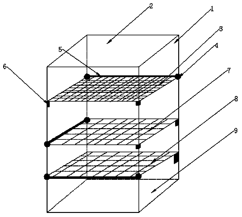
[0017] The present invention will be further described below in conjunction with the accompanying drawings. The square cylinder 1 is made of stainless steel and is used to provide mineral filtering passages. The feeding port 2 is located on the upper part of the square cylinder 1, through which minerals enter the cylinder. The top filter 3, the middle filter 7, and the bottom filter 8 are respectively located at the upper end, middle end, and lower end of the cylinder body 1. One side link 4 is on the rotating shaft 5 on the wall of the rectangular filter device, and the other side passes through the support piece. 6 supports, the entire filter screen is in the horizontal direction, the filter screen can be rotated 5 times through the rotating shaft, and it is convenient to put it down and put it away, and the filter diameter of the three-layer filter screen decreases in turn. The discharge port 9 is located at the bottom of the square cylinder 1, and the separated material i...


PUM


Abstract

The invention relates to a novel combined filtering unit which comprises a square barrel, a feeding port, a top-layer filter screen, a middle-layer filter screen, a bottom-layer filter screen, rotating shafts, supporting pieces and a discharge port. The square barrel is made of stainless steel materials and used for providing a mineral filtering channel; the feeding port is located in the upper portion of the square barrel, and minerals can enter the barrel from the feeding port; the top-layer filter screen, the middle-layer filter screen and the bottom-layer filter screen are located at the upper end, middle end and lower end of the barrel respectively, one side of the top-layer filter screen, one side of the middle-layer filter screen and one side of the bottom-layer filter screen are linked to the rotating shafts on the wall face of the rectangular filtering unit, the other side of the top-layer filter screen, the other side of the middle-layer filter screen and the other side of the bottom-layer filter screen are supported through the supporting pieces, and all the filter screens are located on the horizontal direction; the rotating shafts are fixedly arranged on the wall face of the square barrel and serve as movable rotating shafts of the filter screens; the discharge port is located in the bottom of the square barrel, and materials are discharged from the discharge port. A plurality of filter screens with different meshes are arranged in the novel combined filtering unit, the minerals can be separated in a multi-grade mode in the different filter screens, and the novel combined filtering unit has the advantages of being high in abrasive resistance, good in adjustment performance, simple in structure, and convenient to manufacture.

Description

technical field [0001] The invention relates to a novel combined filter device, in particular to a filter device used in mineral separation. Background technique [0002] A method of separating different mineral particles in mineral separation is to pass materials through filters of different meshes, and separate materials of different particle sizes according to different flow gaps in the filters. At present, in some small-scale mineral separation, a single filtration separation method is adopted, and the separation is only carried out in a filter screen of one mesh. During the separation process, the filter screen is often fixed in the filter device, which is not easy to replace and maintain, especially in When the particle size of mineral particles differs greatly, this separation method will cause insufficient separation, and minerals with different particle sizes cannot be separated well, which reduces the separation efficiency. Therefore, it is particularly important ...

Claims


Application Information

Patent Timeline
IPC IPC(8): B07B1/04B07B1/46
Inventor 赫川陈祥武李玉丹
Owner 天津聚贤达科技有限公司
Learn More