Novel assembling and welding process of spiral shaft of high-weir type double-spiral classifier

A double helix and classifier technology, applied in welding equipment, manufacturing tools, metal processing equipment, etc., can solve problems such as large vibration, large noise, and poor manufacturing accuracy of the screw shaft

Inactive Publication Date: 2013-12-11
王艳宜
View PDF1 Cites 2 Cited by
  • Summary
  • Abstract
  • Description
  • Claims
  • Application Information

AI Technical Summary

Problems solved by technology

This traditional manufacturing process is labor-intensive and time-consuming, which makes the manufacturing cost of the screw shaft high, and it does not necessarily guarantee high assembly accuracy after precision machining is used in manufacturing.
The manufacturing difficulty is mainly due to the fact that the screw shaft is very long and heavy. After welding and assembly, due to the misalignment of manufacturing benchmarks, inspection benchmarks, and assembly benchmarks, the journal protrudes from one end of the hollow shaft during welding and will sag due to length and weight. The center line of the hollow shaft forms an included angle, causing the radial circular runout of the hollow shaft and the journal to be far out of tolerance
As a result, the reinforcing ribs, the flange and the center line of the hollow shaft do not necessarily coincide, making the manufacturing accuracy of the screw shaft poor
If such a screw shaft is mounted on the classifier, the large vibration and noise will be generated due to the large coaxiality error of the screw shaft when the classifier is running.
The screw shaft produced by the traditional manufacturing process cannot really achieve the purpose of qualified products
[0003] The new process method of welding the spiral shaft of the high weir double-helix classifier solves the problem that the coaxiality of each component after welding is high in the traditional manufacturing process, and the traditional manufacturing process is difficult to achieve.

Method used


Image

  • Novel assembling and welding process of spiral shaft of high-weir type double-spiral classifier
  • Novel assembling and welding process of spiral shaft of high-weir type double-spiral classifier
  • Novel assembling and welding process of spiral shaft of high-weir type double-spiral classifier

Examples


Embodiment Construction

[0011] The present invention will be described in further detail below in conjunction with the accompanying drawings and specific embodiments.

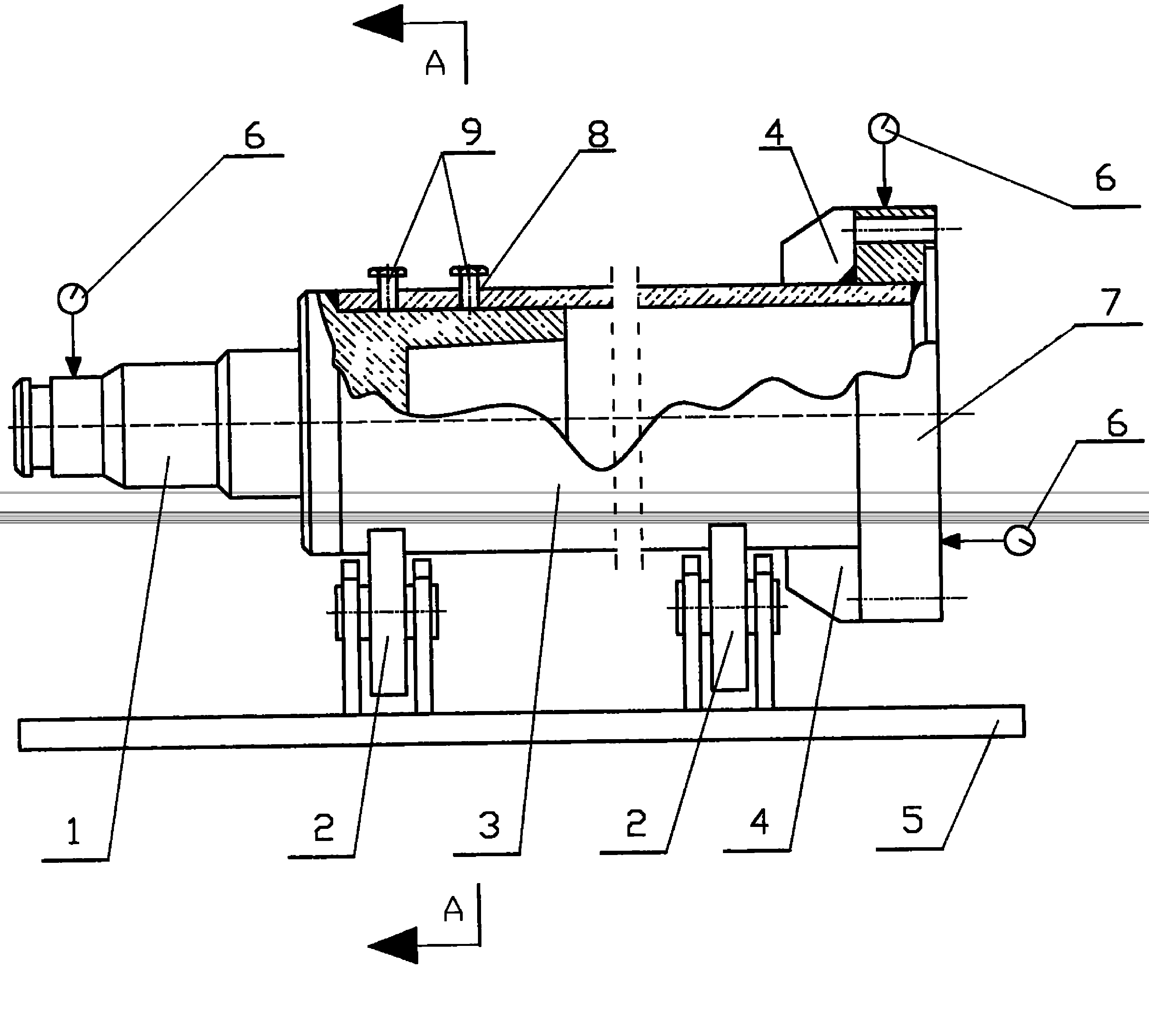
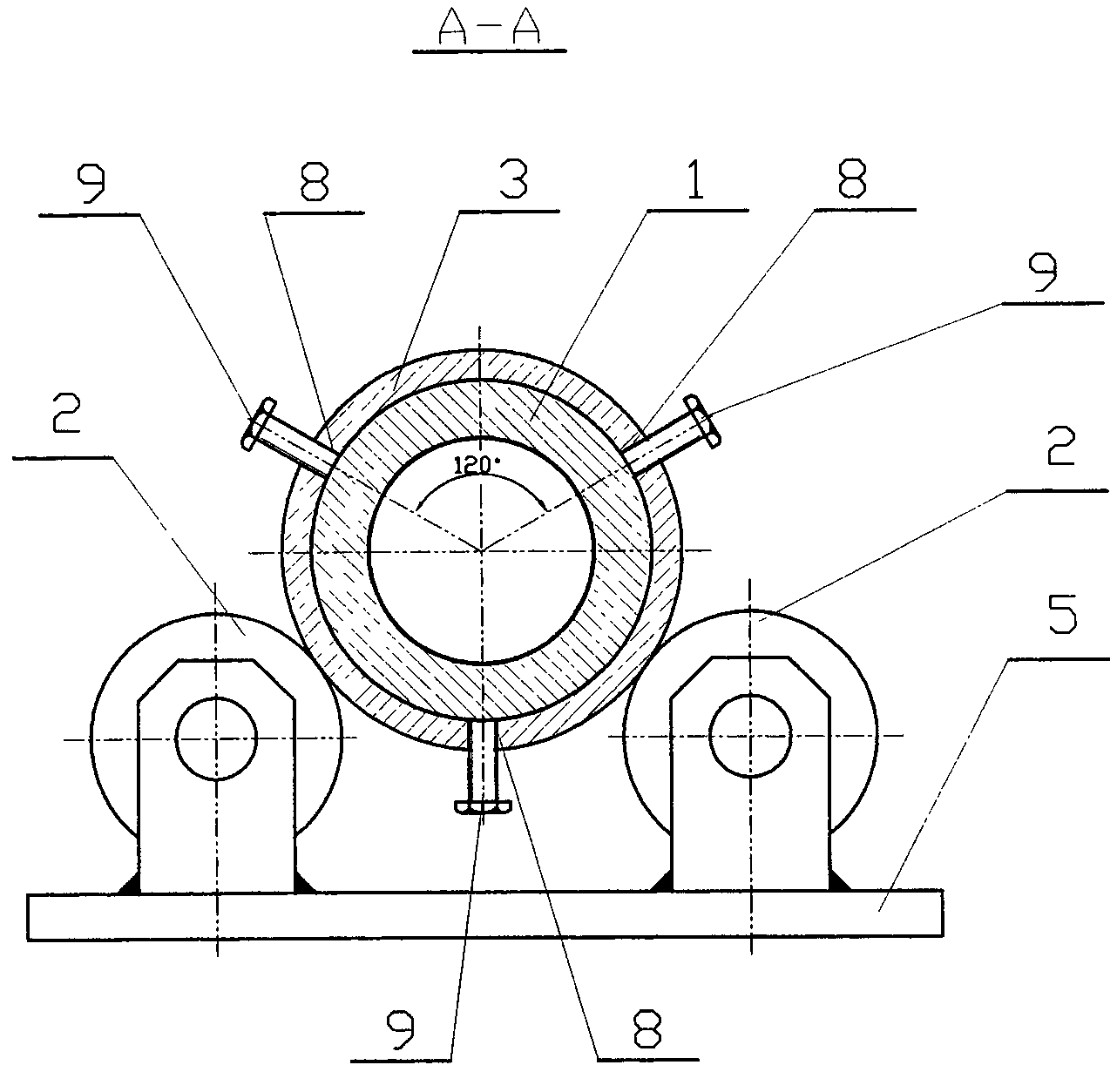
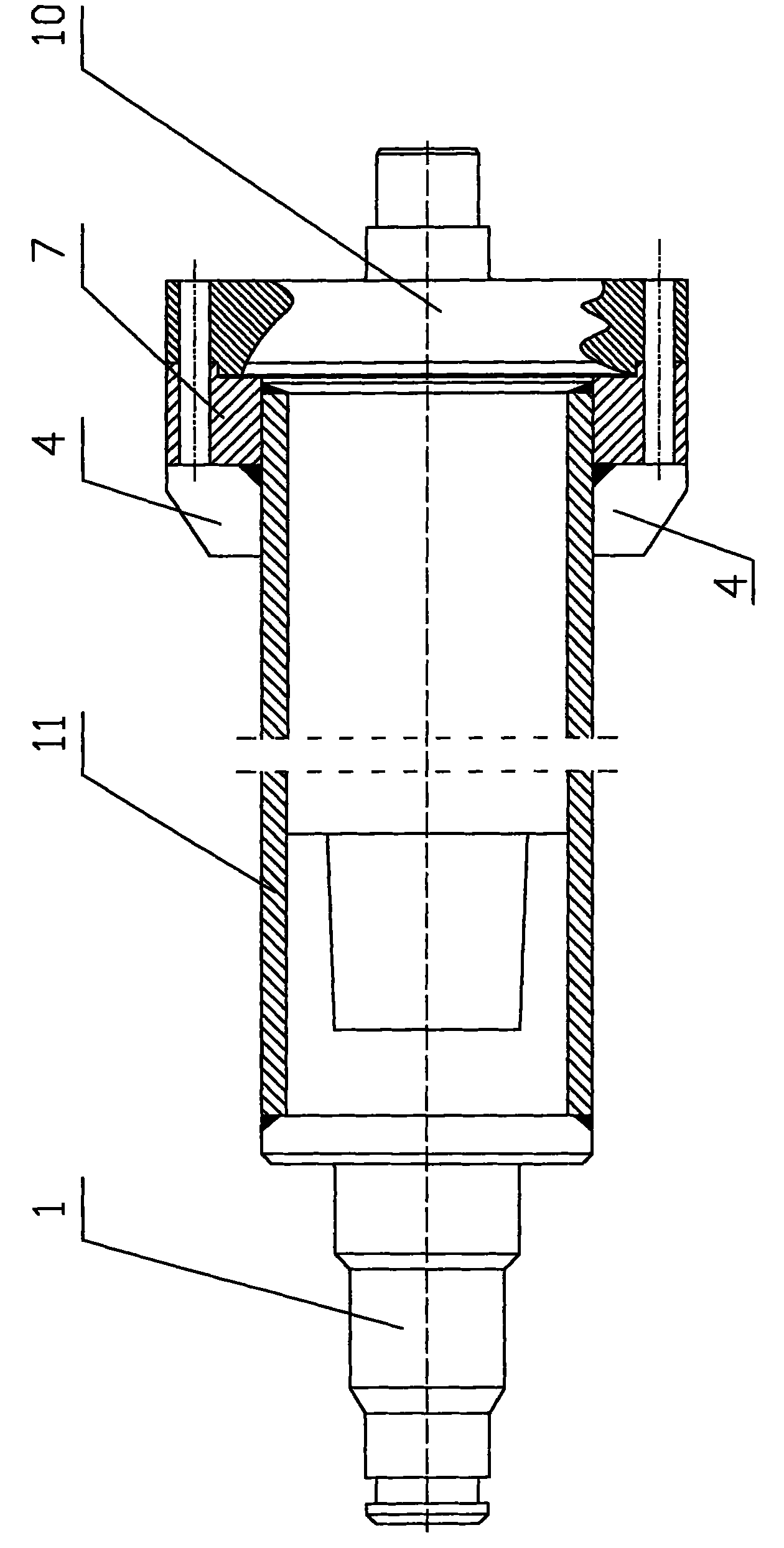
[0012] refer to image 3 , the screw shaft of the high weir double-screw classifier is mainly composed of three parts: journal 1, hollow shaft 11, and tail shaft 10. Perform precision machining. Then the journal 1 and the hollow shaft 11 are assembled and welded into one, the reinforcing rib 4, the flange 7 and the hollow shaft 11 are welded into one and then precision machining is carried out, and the tail shaft 10 is assembled with the flange 7 with bolts. This traditional manufacturing process is labor-intensive and time-consuming, which makes the manufacturing cost of the screw shaft high, and it is difficult to ensure high manufacturing accuracy after processing. The main difficulty in manufacturing is that the screw shaft is very long and heavy. After welding and assembly, due to the misalignment of the manufacturing benchmark...


PUM


Abstract

The invention relates to a novel welding process in machine manufacturing and solves the problems of high coaxiality requirement of each component after assembling and welding in the process of manufacturing by using a traditional method and difficulty of a traditional manufacturing process in meeting the requirement. By using the novel assembling and welding process of the spiral shaft of the high-weir type double-spiral classifier, the traditional manufacturing process for producing long-shaft assembling and welding parts is changed, the production process is simplified, the production cost is reduced, and the product quality is improved. Thus, when the spiral-shaft type classifier is operated, the vibration is less, the noise is low, the rotating speed can be increased, so as to increase the production efficiency, the service life of a bearing can be prolonged, and the service life of the spiral classifier is greatly prolonged.

Description

【Technical field】 [0001] The present invention relates to a new welding process in mechanical manufacturing, specifically a new welding process for the screw shafts of a high-weir type double-helix classifier. Process two threaded holes, use bolts to screw into the threaded holes to adjust the circular runout of the long shaft, and then segmentally weld the shaft head to replace the traditional manufacturing process of long shaft assembly welding. Solve the problems of low coaxiality, large circle runout and difficult manufacturing in the traditional manufacturing process. 【Background technique】 [0002] As we all know, the particle size classification in the beneficiation process of various metal ore and non-metallic ore uses a spiral classifier to classify minerals with different particle sizes in the water medium with different sedimentation velocities. Spiral classifiers can be divided into high-weir type and submerged type. The screw shaft of high-weir type double-scre...

Claims


Application Information

Patent Timeline
Patent Type & Authority Applications(China)
IPC IPC(8): B23K31/02
Inventor 王艳宜
Owner 王艳宜
Why Eureka
Try Eureka