Parallel scanning laser preprocessing device and method

A preprocessing device and scanning laser technology, applied in the field of optics, can solve the problems of uncontrollable component preprocessing, uneven irradiation, and inability to monitor scanning points in real time, compressing the preprocessing time period, and solving uneven reflected irradiation. , The effect of raising the laser damage threshold

Inactive Publication Date: 2016-02-17
成都精密光学工程研究中心
View PDF4 Cites 0 Cited by
  • Summary
  • Abstract
  • Description
  • Claims
  • Application Information

AI Technical Summary

Problems solved by technology

The single-point point-by-point scanning method has the disadvantage of taking a long time
Simple use of multiple total reflections of the laser beam for scanning can improve efficiency, but this method cannot monitor the status of all scanning points in real time. Once damage occurs at a certain reflection point during the scanning process, the energy of other reflection points will change sharply, resulting in The problem of uneven irradiation leads to uncontrollable pretreatment of the entire component, and the effect cannot meet the requirements

Method used


Image

  • Parallel scanning laser preprocessing device and method
  • Parallel scanning laser preprocessing device and method
  • Parallel scanning laser preprocessing device and method

Examples


Embodiment Construction

[0023] Below in conjunction with embodiment the present invention is further described.

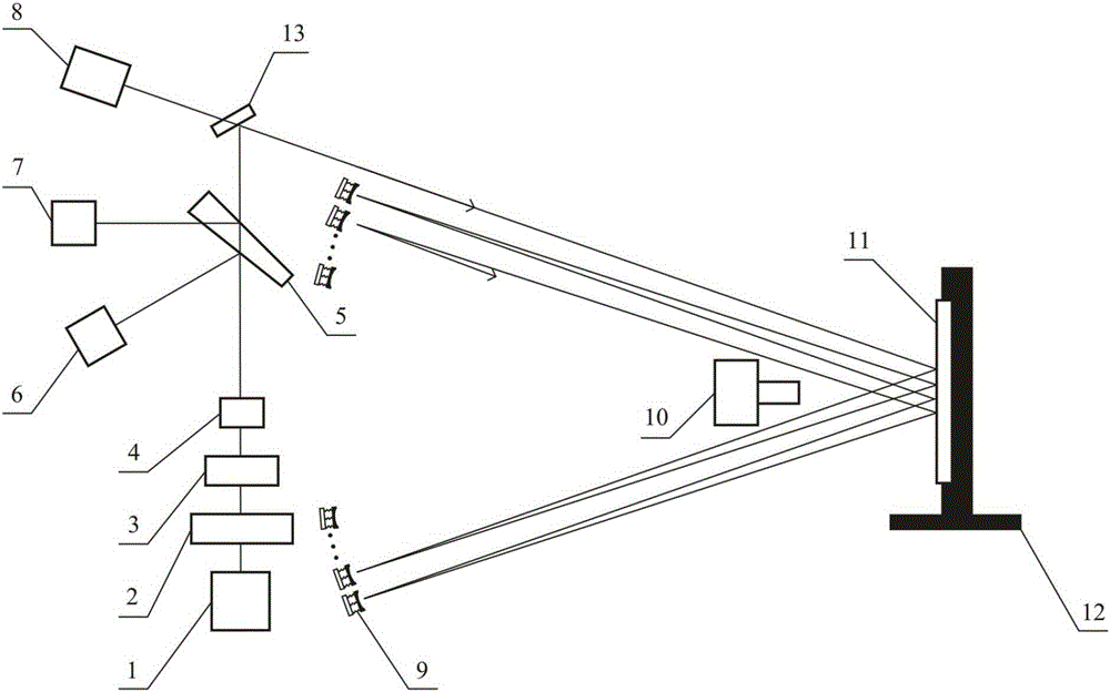
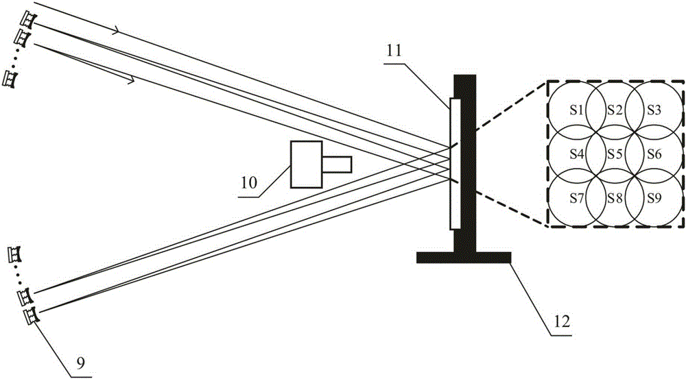
[0024] see figure 1 ---4, parallel scanning laser preprocessing device, including laser light source 1, mechanical shutter 2, energy attenuator 3, beam converging system 4, beam splitter 5 and beam combiner 13 arranged along the laser transmission direction, and also includes a beam profiler 6. Laser energy meter 7, beacon light source 8 and electric displacement stage 12; optical element 11 is placed on electric displacement stage 12; a tilting mirror array 9 is arranged between the device and optical element 11, and a detection camera is arranged in front of optical element 11 10.

[0025] The laser light source 1 is a Q-switched solid-state laser. The beacon light source 8 is a helium-neon laser. The mirror surface of the tilting mirror array 9 is a concave mirror coated with a high reflection film.

[0026] The angle (degree of freedom) control of the tilting mirror array 9 is dri...


PUM


Abstract

The invention discloses a parallel scanning laser pretreatment device and a parallel scanning laser pretreatment method, belonging to the field of optical technologies. The parallel scanning laser pretreatment device comprises a laser light source, a mechanical shutter, an energy attenuator, a light beam converging system, a light splitting plate and a beam combining mirror which are arranged along the laser transmission direction. The parallel scanning laser pretreatment device further comprises a light beam contourgraph, a laser energy meter, a beacon light source and an electric displacement platform, wherein an optical element is arranged on the electric displacement platform, an tilting mirror array is arranged between the parallel scanning laser pretreatment device and the optical element, and a detection camera is arranged in front of the optical element. According to the parallel scanning laser pretreatment device, the pretreatment efficiency is increased by repeatedly using laser energy, the problem of nonuniform reflection irradiation caused by damage is solved, and a laser-damaged threshold of the large-calibre optical element can be effectively increased at a high speed.

Description

technical field [0001] The invention relates to an optical element processing device and method, especially its laser pretreatment, and belongs to the field of optical technology. Background technique [0002] After the optical components are manufactured, laser pretreatment is required. At present, small-caliber, millimeter-scale laser spots are mainly used to uniformly irradiate the thin-film components through raster scanning. Because the two factors of irradiation uniformity and flux increase will affect the effect of laser pretreatment, in order to ensure that a large-aperture optical element can receive uniform irradiation, usually during the scanning process, the spot spacing should not be too large, so that twice There is a certain overlap between irradiations to ensure that there are no blind spots in the scan. At the same time, it is necessary to gradually increase the flux to induce the pretreatment effect gently. These two factors lead to the shortcoming of tim...

Claims


Application Information

Patent Timeline
Patent Type & Authority Patents(China)
IPC IPC(8): B29C71/04
Inventor 马平郑轶刘志超浦云体王刚
Owner 成都精密光学工程研究中心
Why Eureka
Try Eureka