Radiant heating system with a high infrared radiant heating capacity, for treatment chambers

Inactive Publication Date: 2006-06-27
CENTROTHEM PHOTOVOLTAICS AG
View PDF7 Cites 16 Cited by
  • Summary
  • Abstract
  • Description
  • Claims
  • Application Information

AI Technical Summary

Benefits of technology

[0010]To achieve a uniform irradiation of a large area, an array of infrared radiation units with infrared radiation sources may be provided. Each infrared radiation source may be separately connectable to an energy source, in order to make possible a simple adaptation of the radiation output as needed, e.g. by cutting in the requisite number of infrared radiation sources from time to time.
[0020]In an advantageous embodiment of the invention, each infrared radiation source is separately connectable to an energy source. In the case of arrays of large area, this permits a simple adaptation of the radiation output as needed from time to time, for example by changing the number of infrared radiation sources required in each instance.

Problems solved by technology

Such radiant heating systems, however, have been found to have some disadvantages, considerably limiting their application.
First, there is the problem that, especially in vacuum applications, electrical breakdown may occur at high operating voltages.
This hazard arises especially during the process of evacuation.
Second, especially high working temperatures and / or radiation outputs may be unattainable in a vacuum due to lack of adequate cooling of the infrared emitters.
To avoid breakdowns, the voltage may of course be reduced, but then the requisite radiation output cannot be attained.
Besides, there is the possibility that the heating of the vacuum chamber may be cut off during evacuation.
But this necessarily leads to an undesirable increase, or prolongation, of processing time.

Method used


Image

  • Radiant heating system with a high infrared radiant heating capacity, for treatment chambers
  • Radiant heating system with a high infrared radiant heating capacity, for treatment chambers
  • Radiant heating system with a high infrared radiant heating capacity, for treatment chambers

Examples


Embodiment Construction

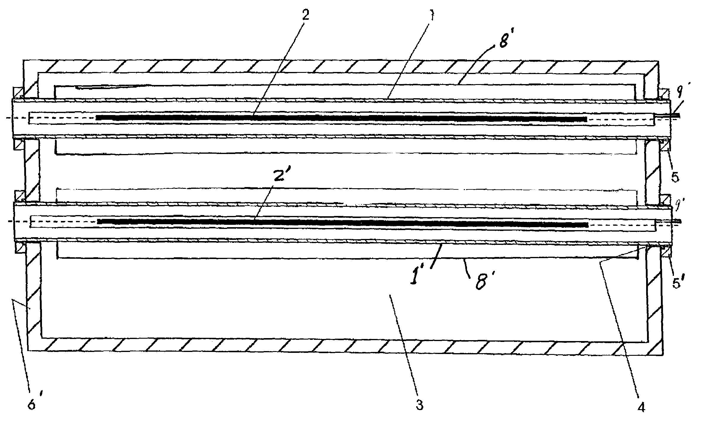
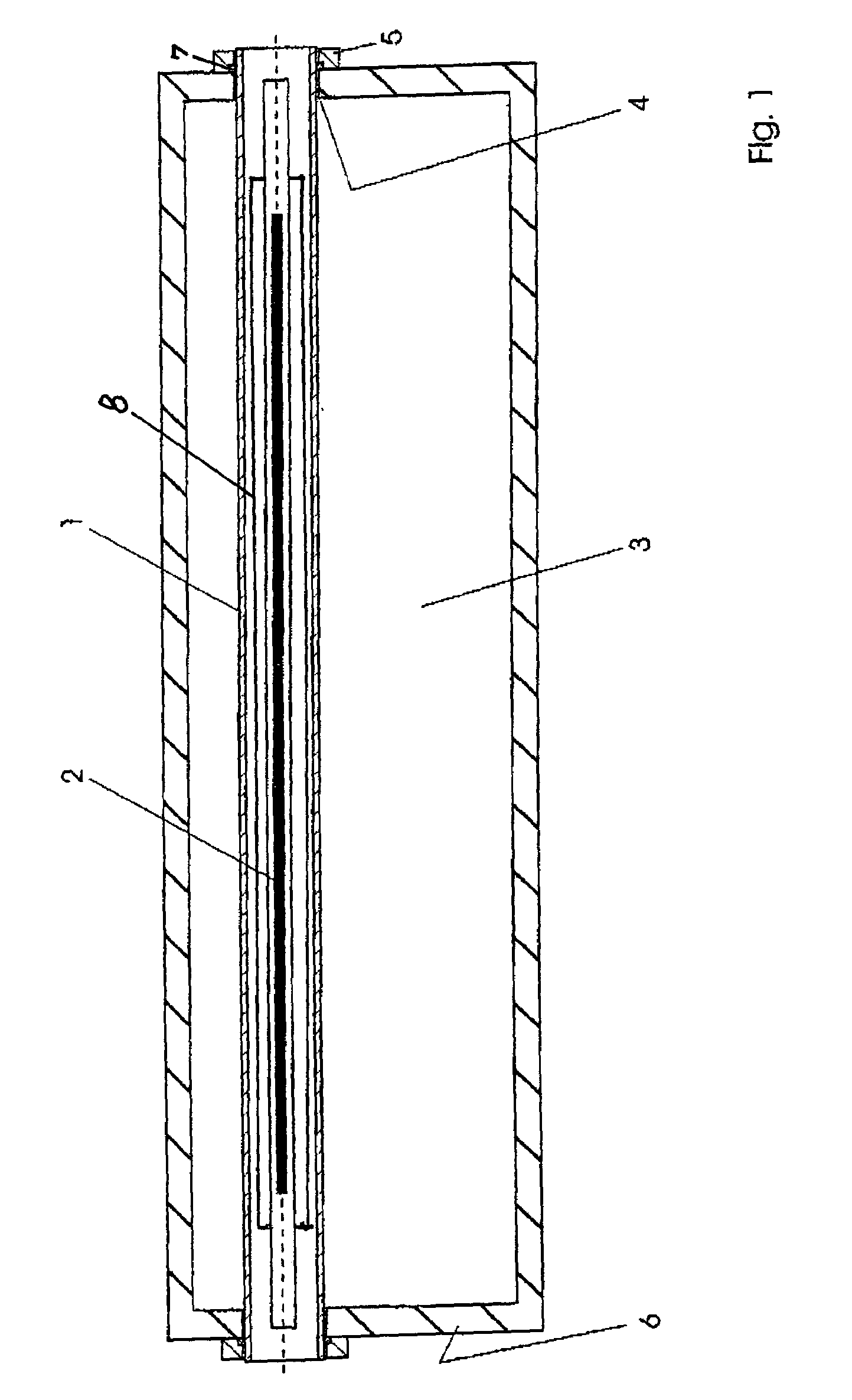
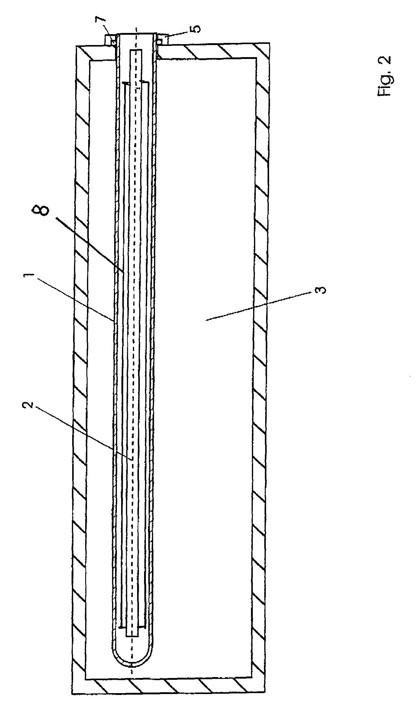
[0025]The radiation heating arrangement according to a first embodiment of the invention consists, in FIG. 1, of a tube 1 transmissive to infrared radiation, extending through a processing chamber 3 and piercing its wall 6 through an aperture 4 at each end. Inside the tube 1, an infrared radiation source 2 is arranged, isolated from the atmosphere inside the processing chamber 3. This tube 1 consists of a highly temperature-resistant material, preferably quartz glass. The tube includes an internal infrared reflector 8.

[0026]To rule out any disturbance of the atmosphere inside the processing chamber 3, the places where the tube 1 passes through the wall 6 are sealed airtight. For this purpose, a closure 5 is provided with an internal seal 7.

[0027]Further, the infrared radiation source 2 in the tube 1 is connected to a source of cooling air which is not shown. For example, the tube 1 may be connected to a unit for generating a flow of air inside the tube 1. In this way, high radiation...


PUM

PropertyMeasurementUnit
Permeabilityaaaaaaaaaa
Energyaaaaaaaaaa

Abstract

A radiant heating arrangement with a high infrared heating capacity for treatment chambers provides a vacuum-compatible radiant heating system with which it is possible to achieve considerable radiation levels reliably. The radiant heating arrangement includes a tube that is permeable to infrared radiation. The tube extends into the treatment chamber and penetrates the wall of the chamber with at least one end. A source of infrared radiation is situated inside the tube with the inside of the tube being isolated from the atmosphere inside the treatment chamber.

Description

BACKGROUND OF THE INVENTION[0001]The invention relates to a radiant heating system having a high infrared heating capacity for processing chambers.[0002]Such radiant heating systems are employed for example inside of processing chambers, e.g. vacuum chambers, in order to generate a requisite working temperature in a given space. Such temperatures may easily reach 3000° C. in the emitter region, and in the case of spaces of great area, an “array” having a plurality of emitters may alternatively be used, in order to achieve a uniform working temperature over a larger space.[0003]Such radiant heating systems, however, have been found to have some disadvantages, considerably limiting their application. First, there is the problem that, especially in vacuum applications, electrical breakdown may occur at high operating voltages. This hazard arises especially during the process of evacuation. Second, especially high working temperatures and / or radiation outputs may be unattainable in a va...

Claims


Application Information

Patent Timeline
IPC IPC(8): F27B5/14H05B3/00H05B3/44
CPCH05B3/0038H05B3/44H05B2203/032
Inventor VOLK, HANS-PETERREICHART, JOHANN GEORGE
Owner CENTROTHEM PHOTOVOLTAICS AG
Why Eureka
Try Eureka