Thermal Energy Deburring Machine Tool Hydraulic System and Its Control Method

A thermal energy deburring and hydraulic system technology, applied in the direction of mechanical equipment, fluid pressure actuators, servo motors, etc., can solve problems such as dangerous accidents, casualties, equipment damage, etc., and achieve strong safety, large leakage, and energy consumption reduction effect

Active Publication Date: 2015-08-19
NANJING BIJUR MACHINERY PRODS
View PDF4 Cites 0 Cited by
  • Summary
  • Abstract
  • Description
  • Claims
  • Application Information

AI Technical Summary

Problems solved by technology

When an explosion occurs, the combustion chamber components must form a reliable airtight space, and any leakage will cause dangerous accidents, resulting in damage to equipment and even casualties

Method used


Image

  • Thermal Energy Deburring Machine Tool Hydraulic System and Its Control Method

Examples


Embodiment 1

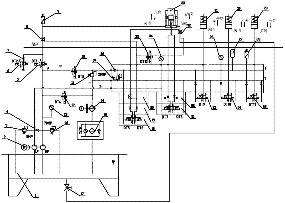
[0036]The technical solution of the present invention will be described in further detail below in conjunction with the accompanying drawings.

[0037] like figure 1 , the thermal energy deburring machine tool hydraulic system of the present invention utilizes a double pump system, various valve parts and actuators (hydraulic cylinders) to form three hydraulic circuits of ultra-high pressure, medium pressure and low pressure through pipeline connections, wherein:

[0038] The ultra-high pressure circuit is mainly composed of the high pressure pump in the hydraulic double pump 2, the high pressure relief valve 16, the high pressure gauge 13, the first and second cut-off reversing valves 5, 6, the throttle valve 7, the first hydraulic control unit Composed of direction valve 8, high-pressure pressure sensor 9 and so on. The high-pressure relief valve 16, the high-pressure pressure gauge 13, the first and second cut-off directional valves 5, 6 and the throttle valve 7 are all co...


PUM


Abstract

The invention discloses a hydraulic system of a thermal energy deburring machine tool and a control method of the hydraulic system. According to the hydraulic system, an ultra-high-pressure hydraulic circuit, a medium pressure hydraulic circuit and a low pressure hydraulic circuit are formed by double-pump systems, various valves and executive components for respectively meeting the technical requirements of large-tonnage clamping in a combustion chamber of the machine tool, sealing for mixing valves and rapid clamping in the combustion chamber, wherein the rapid closing and clamping of a base of the combustion chamber are completed mainly through clamping cylinders of the executive components, and the sealing for three valve cores of the mixing valves is completed mainly through gas valve cylinders, oxygen valve cylinders and exhaust valve cylinders of the mixing valves. The hydraulic system has the characteristics of low energy consumption, reliable system, strong safety, rapid and smooth action, simple and compact structure, low cost and easiness in maintenance.

Description

technical field [0001] The invention relates to a hydraulic system and a control method thereof, in particular to a hydraulic system with multiple hydraulic circuits applied to a heat energy deburring machine tool and a control method thereof. Background technique [0002] The thermal energy deburring machine tool uses gas and oxygen to mix and ignite to explode in the combustion chamber, and uses the high temperature and high pressure during the explosion to remove the burrs on the workpiece in the combustion chamber. When an explosion occurs, the combustion chamber components must form a reliable airtight space, and any leakage will cause dangerous accidents, resulting in equipment damage and even casualties. This equipment requires a large tonnage clamping force to clamp the combustion chamber base and the combustion chamber to achieve sealing. At the same time, the channel mixing valve for gas entering and leaving the combustion chamber also needs to press the valve core...

Claims


Application Information

Patent Timeline
Patent Type & Authority Patents(China)
IPC IPC(8): F15B11/17
Inventor 唐郭姜干付程治杰
Owner NANJING BIJUR MACHINERY PRODS
Why Eureka
Try Eureka