Waste heat recovery energy-saving device adapted to boiler chimney and chimney including the device

A waste heat recovery and energy-saving device technology, applied in the field of chimneys, can solve the problems of reducing the life of heat exchange tubes and boilers, reducing the heat transfer efficiency of heat exchange tubes, affecting the efficiency of waste heat recovery in the chimney, etc. Easy to operate effect

Active Publication Date: 2017-01-04
HARBIN ENG UNIV
View PDF6 Cites 0 Cited by
  • Summary
  • Abstract
  • Description
  • Claims
  • Application Information

AI Technical Summary

Problems solved by technology

[0003] The existing boiler flue gas waste heat recovery device is usually installed at the boiler flue outlet, without dust cleaning function, some equipment needs additional power source and related equipment, which will make the initial investment of the equipment relatively large, and cannot achieve good performance. energy saving effect
On the one hand, when the flue gas flowing through the waste heat recovery device of the boiler encounters the low-temperature heat exchange tube, condensed water will be generated on the surface of the heat exchange tube, and the condensed water will easily flow into the boiler. The surface of the boiler and the boiler are highly corrosive, which will reduce the service life of the heat exchange tube and the boiler; With the accumulation of time, the dust adsorbed on the heat exchange tube will gradually thicken, which will greatly reduce the heat transfer efficiency of the heat exchange tube and affect the recovery efficiency of the heat exchange tube for the waste heat in the chimney
In addition, the existing boiler flue gas waste heat recovery device welds multiple heat exchange tubes into a box, which is inconvenient for inspection and maintenance, resulting in high maintenance costs in later use

Method used


Image

  • Waste heat recovery energy-saving device adapted to boiler chimney and chimney including the device
  • Waste heat recovery energy-saving device adapted to boiler chimney and chimney including the device
  • Waste heat recovery energy-saving device adapted to boiler chimney and chimney including the device

Examples


Embodiment Construction

[0021] The present invention is described in more detail below in conjunction with accompanying drawing example:

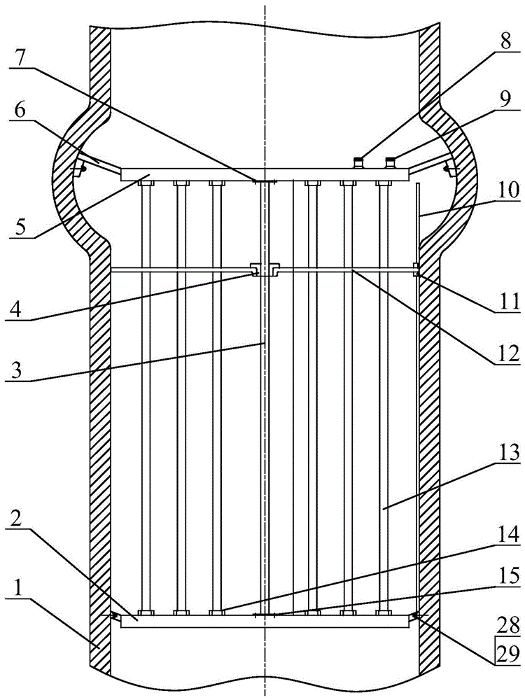
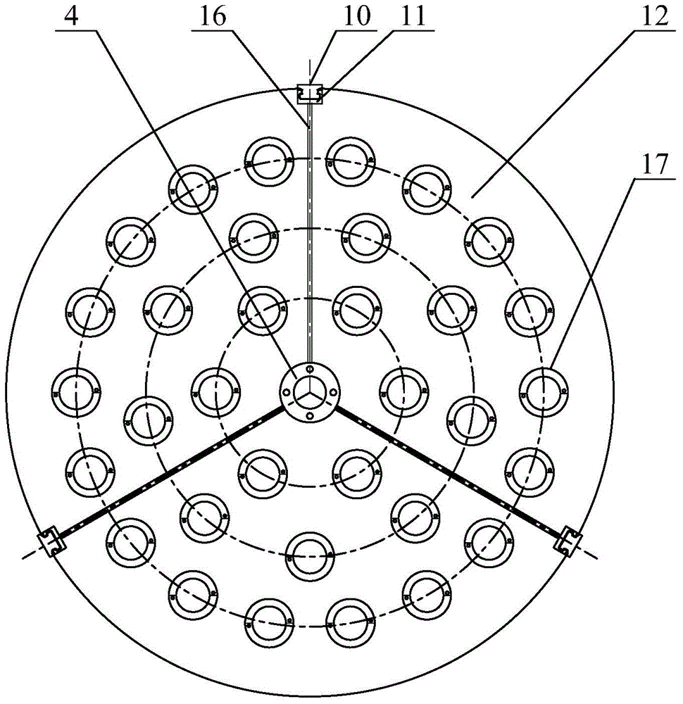
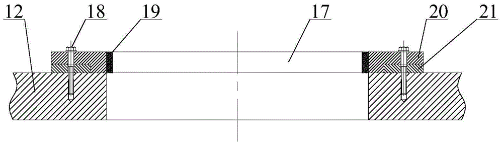
[0022] combine Figure 1~4 , the energy-saving part is the core part of the device, mainly composed of a boiler 23, an air outlet 27, a chimney 1, an inspection port 26, a heat exchange tube 13, an inner wire pipe joint 14, a lower guide ring 2, an upper guide ring 5, an inlet Water outlet 8, water outlet 9, connecting plate 6, connecting plate 28, expansion screw 29, fan 22; Expansion screw 29 is installed in the chimney close to chimney 1 and gas outlet 27 joints, and the position design an inspection hole 26 is installed energy-saving device on chimney. A blower fan 22 is installed at the air inlet of the boiler, which can not only enable the fuel to be fully burned in the boiler but also increase the pressure of the gas at the air outlet to provide greater power for the movement of the sealing disc 12 . When installing the energy-saving device, insert a plur...


PUM


Abstract

The invention aims to provide a waste heat recovery energy-saving device applicable to a boiler chimney and a chimney comprising the same. The waste heat recovery energy-saving device applicable to the boiler chimney comprises an upper conducting ring and a lower conducting ring, wherein a heat exchange pipe is mounted between the upper conducting ring and the lower conducting ring; the upper conducting ring and the lower conducting ring both are in hollow structures, and are communicated with the heat exchange pipe; the upper conducting ring is fixed in an upper position inside the chimney through an upper connecting plate; the lower conducting ring is fixed under a lower position inside the chimney through a lower connecting plate; a water inlet and a water outlet are formed in the upper conducting ring, respectively. The chimney comprising the waste heat recovery energy-saving device applicable to the boiler chimney is characterized in that the section of the inner wall of the chimney is circular, the diameter of the inner wall of the chimney at the upper conducting ring is greater than the diameter of the inner wall of the chimney at other part, and the upper end portion of a guide rail is located at the upper conducting ring. The waste heat recovery energy-saving device applicable to a boiler chimney is capable of increasing the temperature difference during heat exchange; therefore, the temperature rise speed of water in the heat exchange pipe is increased.

Description

technical field [0001] The invention relates to a waste heat recovery energy-saving device and a chimney comprising the energy-saving device. Background technique [0002] Energy is an important material basis for human survival and development. With economic development and further expansion of economic scale, energy demand will grow at a relatively rapid rate. Energy is a prominent bottleneck restricting economic and social development at present and for a long period of time in the future. In order to alleviate the constraints of energy bottlenecks, it is necessary to increase supply, but energy resources are limited, and increasing supply will be restricted by various conditions. The fundamental method is Adhere to the policy of developing and saving simultaneously, giving priority to energy saving, vigorously promote the policy of energy saving and consumption reduction, and improve energy utilization efficiency. [0003] The existing boiler flue gas waste heat recover...

Claims


Application Information

Patent Timeline
Patent Type & Authority Patents(China)
IPC IPC(8): F23J15/06F28D7/10F28G1/02
CPCY02E20/30
Inventor 赵刚许国玉乔东潘李照远孙壮志刘文博隋智阳郭华君饶宇赵华兴
Owner HARBIN ENG UNIV
Why Eureka
Try Eureka