Method for matching longitudinal waves with transverse waves for geophysical exploration

A technology of geophysical prospecting and matching methods, applied in the field of longitudinal and shear wave matching methods and matching devices used in geophysical prospecting, can solve problems such as difficult matching, dependence, and difficult accurate matching, and achieve theoretical reliability, rigorous process, and good matching Effect

A technology of geophysical prospecting and matching methods, applied in the field of longitudinal and shear wave matching methods and matching devices used in geophysical prospecting, can solve problems such as difficult matching, dependence, and difficult accurate matching, and achieve theoretical reliability, rigorous process, and good matching Effect

CN103439739AActive Publication Date: 2013-12-11BGP OF CHINA NAT GASOLINEEUM CORP

Image

  • Method for matching longitudinal waves with transverse waves for geophysical exploration
  • Method for matching longitudinal waves with transverse waves for geophysical exploration
  • Method for matching longitudinal waves with transverse waves for geophysical exploration

Examples


Embodiment 1

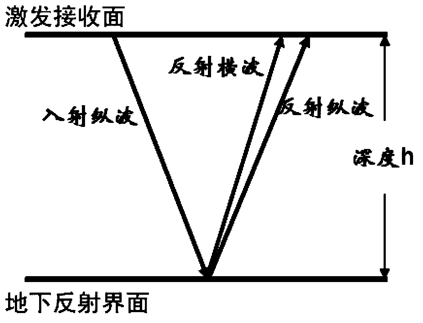
[0049] figure 1It is a schematic diagram of emission after longitudinal wave incident. As shown in the figure, when the incident longitudinal wave encounters the underground reflection interface, it will be reflected, transmitted and converted at the underground reflection interface. The reflected wave includes the reflected longitudinal wave and converted shear wave (reflected shear wave), and the reflected longitudinal wave and converted shear wave are in the The excitation and acceptance surface is accepted, and the depth of the underground reflection interface from the excitation and acceptance surface is h.

[0050] In this embodiment, the propagation characteristics of the PP wave are longitudinal waves in the downward direction and reflected longitudinal waves in the upward direction, and the propagation characteristics of the PS wave are longitudinal waves in the downward direction and reflected transverse waves in the upward direction.

[0051] An embodiment of the p...

Embodiment 2

[0079] Figure 10 It is a schematic diagram of the composition of the longitudinal and transverse wave matching device according to the second embodiment of the present invention. Such as Figure 10 As shown, the longitudinal and shear wave matching device 1000 may include: a phase analysis unit 1001 , a well control processing unit 1002 , a phase correction unit 1003 , a data processing unit 1004 , a time domain conversion unit 1005 , and a fine correction unit 1006 . in:

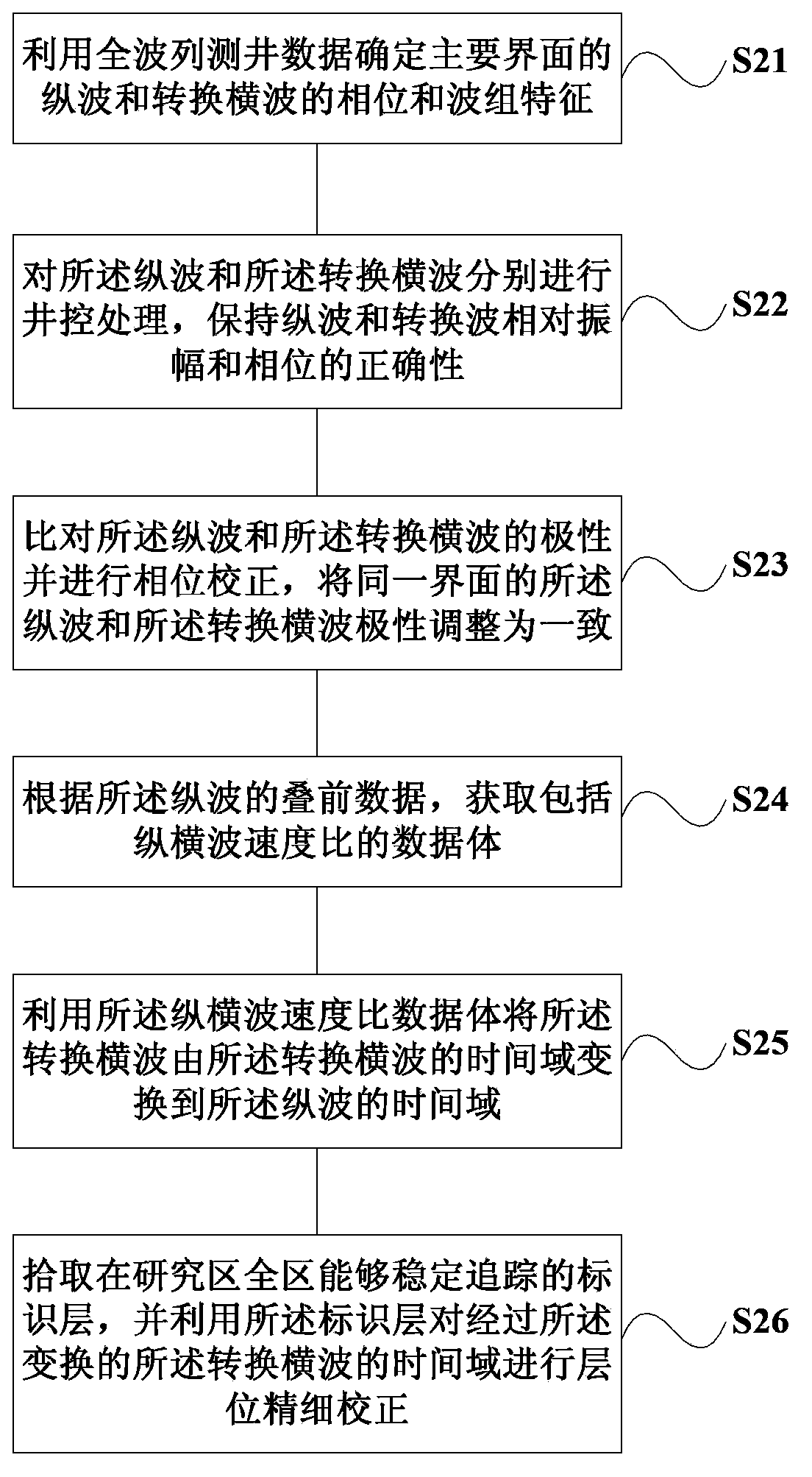
[0080] Phase analysis part 1001, using the full wave train logging data to determine the phase and wave group characteristics of the longitudinal wave and converted shear wave of the main interface;

[0081] The well control processing part 1002 performs well control processing on the longitudinal wave and the converted shear wave respectively, and maintains the correctness of the relative amplitude and phase of the longitudinal wave and the converted shear wave;

[0082] The phase correction unit 1003 ...


PUM


Abstract

The embodiment of the invention provides a method and device for matching longitudinal waves with transverse waves for geophysical exploration. The method includes the steps that full wave train well logging data are utilized to determine phase and wave group characteristics of the longitudinal waves and converted transverse waves in a main interface; well control processing is respectively conducted on the longitudinal waves and the converted transverse waves; the polarity of the longitudinal waves and the polarity of the converted transverse waves are compared and phase correction is conducted; a data body including the speed ratio of the longitudinal waves to the transverse waves is acquired according to prestack data of the longitudinal waves; the data body is utilized to convert the converted transverse waves from the time domain of the converted transverse waves to the time domain of the longitudinal waves; identification layers which can stably track in whole research area are picked up and utilized to conduct fine horizon correction on the converted time domain of the converted transverse waves. The method and device are combined with seismic data processing, forward modeling, inversion and other measures, so that the method and device are reliable in theory and rigorous in process, and the longitudinal waves and the transverse waves can be well matched.

Description

technical field [0001] Embodiments of the present invention relate to a method for matching longitudinal and shear waves, that is, a method for correcting and aligning longitudinal and converted shear waves to the same time domain, and more specifically, a method and device for matching longitudinal and shear waves for geophysical exploration. Background technique [0002] With the gradual deepening of petroleum exploration, the requirements for seismic exploration technology are getting higher and higher, and it has shifted from simple structural exploration to lithology exploration, and from lithology prediction to fluid prediction. Compared with traditional P-wave technology, multi-wave seismic technology has obvious advantages in lithology and fluid prediction. At the same time, with the development of software and hardware technology in recent years, the application of multi-wave is gradually increasing. [0003] Because the propagation modes and paths of longitudinal ...

Claims


Application Information

Patent Timeline
11 Dec 2013
Publication
CN103439739A
IPC
G01V1/28; G01V1/36
Inventors
周义军; 王学军