
Singlechip and on-chip power-on reset circuit thereof

An electric reset, single-chip technology, applied in the field of integrated circuits, can solve the problems of increasing the cost and power consumption of the single-chip microcomputer, the digital system of the single-chip microcomputer cannot work normally, and slow power-on, etc.

Active Publication Date: 2013-12-11
CHIPSEA TECH SHENZHEN CO LTD
View PDF4 Cites 15 Cited by
  • Summary
  • Abstract
  • Description
  • Claims
  • Application Information

AI Technical Summary

Problems solved by technology

[0002] In single-chip microcomputer applications, the power-on reset circuit is used to reset or set digital modules such as counters and registers in the digital system when the power is turned on or off, so the power-on reset circuit is required to have high reliability. The digital system of the single-chip microcomputer cannot work normally due to false reset.
[0003] In the current on-chip power-on reset scheme of single-chip microcomputer, there are schemes for detecting the rising edge of the power supply voltage or the power supply voltage value, or both the rising edge and the voltage value. Under the condition of interference, there are often upward and downward peaks or the power supply is powered on quickly or slowly, etc., often generating false reset signals, affecting the normal operation of the single-chip microcomputer and its digital system
[0004] The existing power-on reset scheme usually adopts an analog integrated circuit scheme, such as an external power-on reset circuit. In order to realize the power-on reset function, an external power-on reset circuit composed of a large capacitor, a large resistor, and a triode is usually used. Or a separate reset chip, however this increases the cost and power consumption of the microcontroller

Method used


Image

  • Singlechip and on-chip power-on reset circuit thereof
  • Singlechip and on-chip power-on reset circuit thereof
  • Singlechip and on-chip power-on reset circuit thereof

Examples


Embodiment Construction

[0035] The technical solutions of the present invention will be further described below in conjunction with the accompanying drawings and specific embodiments. It should be understood that the specific embodiments described here are only used to explain the present invention, not to limit the present invention.

[0036] The invention provides a power-on reset circuit in a single-chip microcomputer.

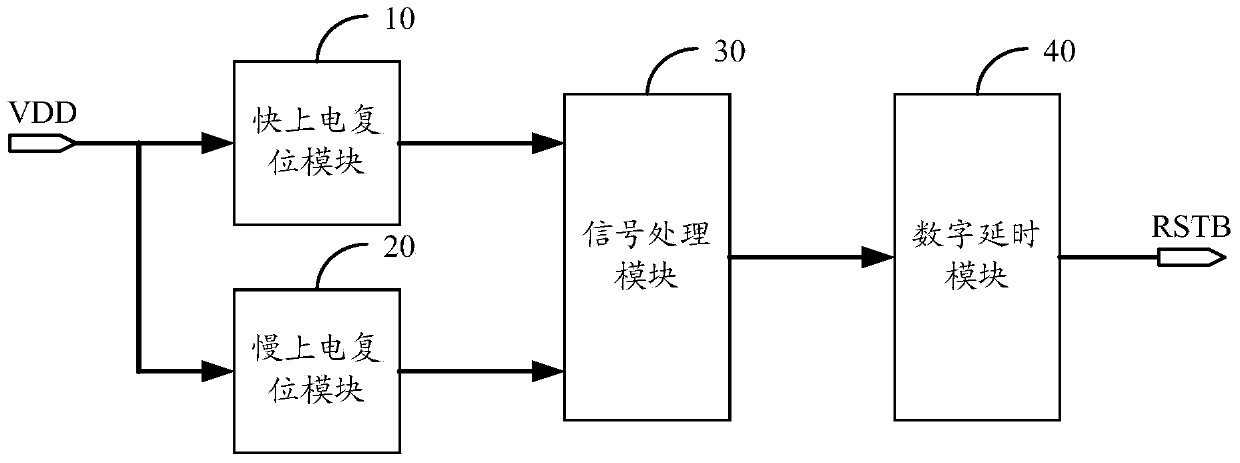
[0037] refer to figure 1 , figure 1 It is a functional block diagram of a preferred embodiment of the on-chip power-on reset circuit in the single-chip microcomputer of the present invention.

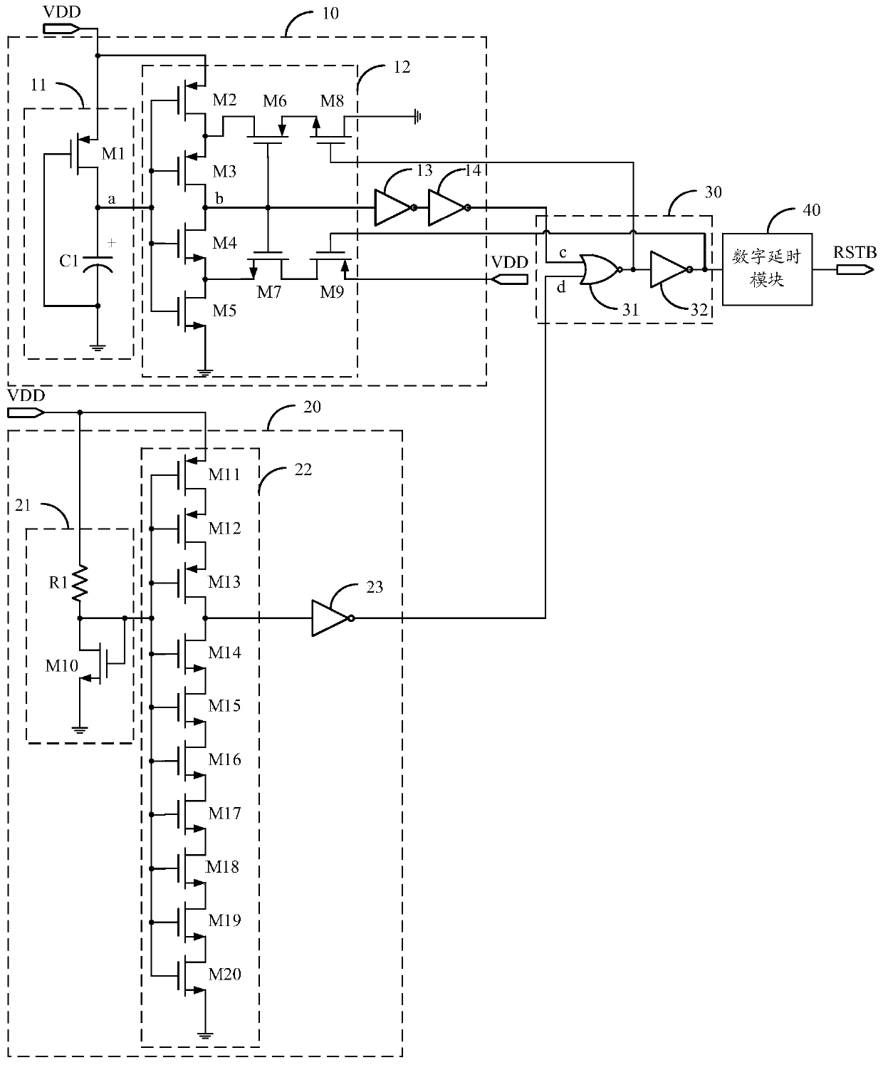
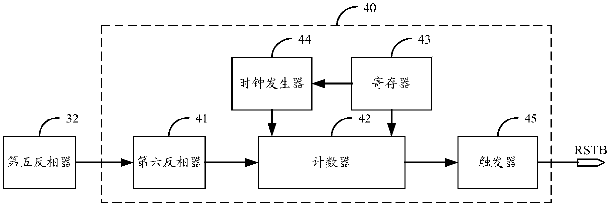
[0038] In a preferred embodiment of the present invention, the on-chip power-on reset circuit of the single-chip microcomputer includes a power input terminal VDD, a reset control terminal RSTB, a fast power-on reset module 10, a slow power-on reset module 20, a signal processing module 30 and a digital delay module 40 . The fast power-on reset module 10 is used to generate a fast power...


PUM


Abstract

The invention discloses a singlechip and an on-chip power-on reset circuit of the singlechip, wherein the on-chip power-on reset circuit of the singlechip comprises a power supply input end, a reset control end, a fast power-on reset module, a slow power-on reset module, a signal processing module and a digital delay module. According to the on-chip power-on reset circuit of the singlechip, disclosed by the invention, the signal processing module takes or handles on a fast power-on reset signal generated by the fast power-on reset module and a slow power-on reset signal generated by the slow power-on reset module to generate a reset control signal, and the reset control signal is output to the digital delay module for being delayed, therefore, a stable and correct reset control signal is obtained, the singlechip is prevented from being wrongly reset to influence normal working, and the work stability and reliability of the singlechip are improved; meanwhile, a reset function can be achieved without using a large capacitor, thus the design cost and power consumption of the singlechip are reduced, and the singlechip can be more effectively prevented from wrongly resetting under the condition that a power supply environment is rugged.

Description

technical field [0001] The invention relates to the technical field of integrated circuits, in particular to a single-chip microcomputer and its on-chip power-on reset circuit. Background technique [0002] In single-chip microcomputer applications, the power-on reset circuit is used to reset or set digital modules such as counters and registers in the digital system when the power is turned on or off, so the power-on reset circuit is required to have high reliability. Sex, and the problem that the digital system of the single-chip microcomputer cannot work normally due to false reset cannot occur. [0003] In the current on-chip power-on reset scheme of single-chip microcomputer, there are schemes to detect the rising edge of the power supply voltage or the power supply voltage value, or both the rising edge and the voltage value. Under the condition of interference, there are often upward and downward spikes or fast power-on or slow power-on of the power supply, etc., whi...

Claims


Application Information

Patent Timeline
IPC IPC(8): G06F1/24
Inventor 谭迁宁乔爱国
Owner CHIPSEA TECH SHENZHEN CO LTD
Learn More