
Novel multipurpose solar concentration system

A concentrating solar energy and multi-purpose technology, applied in the direction of photovoltaic power generation, light radiation generator, photovoltaic thermoelectric hybrid power generation, etc., can solve the problems of low energy utilization rate and single form of energy utilization, so as to improve the utilization rate of sunlight, The effect of reducing technical difficulty and reducing the influence of negative factors

Active Publication Date: 2013-12-11
SHANGHAI NEW IND OPTOELECTRONICS TECH
View PDF4 Cites 11 Cited by
  • Summary
  • Abstract
  • Description
  • Claims
  • Application Information

AI Technical Summary

Problems solved by technology

[0007] In order to solve the problems in photovoltaic power generation and photothermal power generation systems where the full spectrum of sunlight is mixed together, the energy utilization form is single, and the energy utilization rate is not high, the purpose of this invention is to provide a new multi-purpose concentrated solar energy system , can divide the solar spectrum into two parts for application, one part of the light of the shorter band is used for lighting or photovoltaic power generation, and the excess heat is reused through the cooling system, such as providing hot water, heating, etc.; the other part is longer The light in the wavelength band is used for photothermal power generation or to provide hot water, heating, etc., which not only reduces the influence of negative factors in each application method, reduces the technical difficulty of each application method, but also realizes the protection of solar energy. The comprehensive utilization of sunlight improves the utilization rate of sunlight

Method used


Image

  • Novel multipurpose solar concentration system
  • Novel multipurpose solar concentration system

Examples


Embodiment Construction

[0030] The specific embodiments of the present invention will be described below in conjunction with the accompanying drawings.

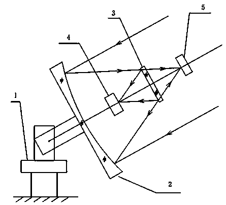
[0031] See attached figure 1 , the main reflector 2 is installed on the support frame 1, and can do two-dimensional real-time movement to track the sunlight, so as to ensure that the sunlight is always incident on the surface of the main reflector 2 along the optical axis of the main reflector 2; the main reflector 2 is non- A spherical mirror or a spherical mirror can obtain a smaller focused spot; the surface of the main reflector 2 is coated with a high-reflectivity coating, which reflects most of the sunlight to the beam splitter 3 .

[0032] Beam splitter 3 can be plane mirror, also can be spherical mirror or aspherical mirror; The area of ​​the beam splitter 3 is larger than the maximum area of ​​the projected light spot of the reflected light of the main reflector 2 on its surface.

[0033] The beam splitter 3 divides the sunlight reflected...


PUM


Abstract

The invention relates to a novel multipurpose solar concentration system which is provided with a main reflecting mirror used for tracking the sun in real time, and a light splitting mirror used for concentrating sunlight between the main reflecting mirror and the focus of the main reflecting mirror. Sunlight is divided into two parts to apply by the light splitting mirror according to a spectrum. Short wave light is reflected by the light splitting mirror and is concentrated on a photovoltaic battery to carry out photovoltaic power generation, and redundant heat is utilized to provide hot water and heat and the like; or is concentrated on a light guide pipe for lighting. Long wave light is transmitted via the light splitting mirror and is concentrated on a photo-thermal receiver, and heat is transmitted to a thermal storage device via a working medium so that heat can be extracted when heat is needed, and an electric generator is driven by a heat engine to perform photo-thermal power generation or to provide hot water and heat and the like. A dividing wavelength of long wave light and short wave light is corresponding to the wavelength determined by a forbidden bandwidth of the photovoltaic battery. Sunlight energy comprehensive utilization which integrates multiple application modes as a whole is realized so that sunlight utilization rate is enhanced.

Description

technical field [0001] The invention relates to a novel multipurpose concentrating solar energy system, which belongs to the technical field of comprehensive solar thermal utilization. Background technique [0002] Solar energy is an extremely abundant clean energy, which is environmentally friendly and inexhaustible. The total amount of solar energy received by the earth every year is more than 10,000 times the total annual energy consumed by the world. The prospect of solar energy utilization is very attractive, and it can be applied to many fields such as lighting, power generation, heating, hot water supply, refrigeration, and seawater desalination. [0003] At present, there are two main forms of solar energy utilization: solar photovoltaic power generation and photothermal power generation. [0004] Solar photovoltaic power generation refers to the technology of directly converting sunlight into electrical energy through photovoltaic cells. Since flat-panel photovolt...

Claims


Application Information

Patent Timeline
Patent Type & Authority Applications(China)
IPC IPC(8): H01L31/052H01L31/058H02N6/00
CPCY02E10/50Y02E10/60
Inventor 缪同群张贵彦伍志军王志洲刘宝星张声荣夏长华
Owner SHANGHAI NEW IND OPTOELECTRONICS TECH
Learn More