


Quick Research
Generate reliable direction feasibility study reports for your R&D in just a few steps.

Technical Q&A
Discover and master advanced knowledge NOW. Basics, ideas, possibilities, all at once.

Find Solutions
As an expert in R&D theories, this can generate solutions to your technical problems instantly.

Evaluate Feasibility
Analyze your overall solution with one click, know your potential R&D risks in advance.

Monitor Landscape
Get weekly tech updates, stay abreast of the latest tech innovations and key insights.
Graphitized cathode block having an abrasion-roof surface
A cathode block and graphitization technology, applied in the field of cathode blocks, can solve the problems of fragile coating, short service life, easy cracking, etc.
- Summary
- Abstract
- Description
- Claims
- Application Information
AI Technical Summary
Problems solved by technology
Method used
Image

Examples
Embodiment Construction
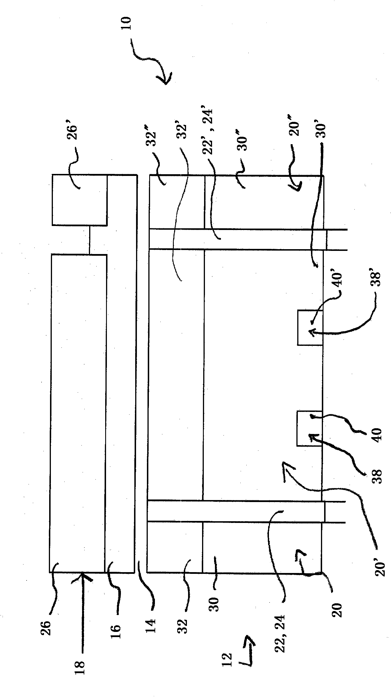
[0057] figure 1 A cross section showing details of an aluminum electrolytic cell 10 with a cathode 12 simultaneously forming the bottom of a tank for the aluminum melt 14 produced during operation of the electrolytic cell 10 and for the Cryolite-alumina melt 16 above aluminum melt 14 . The anode 18 of the electrolytic cell 10 is in contact with the cryolite-alumina melt 16 . The tank formed by the lower part of the aluminum electrolysis cell 10 is lined at the sides with carbon and / or graphite (at figure 1 not shown) defined.
[0058] The cathode 12 comprises a plurality of cathode blocks 20, 20', 20'' which are each connected to each other by ramming materials 24, 24' which have been inserted into the , 20'' between the ramming material joints 22, 22'. Similarly, the anode 18 includes a plurality of anode blocks 26 , 26 ′ each having approximately twice the width and approximately half the length of the cathode blocks 20 , 20 ′, 20 ″. In this case, the anode blocks 26 , ...
PUM
| Property | Measurement | Unit |
|---|---|---|
| melting point | aaaaa | aaaaa |
| crystal size | aaaaa | aaaaa |
| specific surface area | aaaaa | aaaaa |
Abstract
Description
Claims
Application Information
 - R&D Engineer
- R&D Manager
- IP Professional
- Industry Leading Data Capabilities
- Powerful AI technology
- Patent DNA Extraction
Browse by: Latest US Patents, China's latest patents, Technical Efficacy Thesaurus, Application Domain, Technology Topic, Popular Technical Reports.
© 2024 PatSnap. All rights reserved.Legal|Privacy policy|Modern Slavery Act Transparency Statement|Sitemap|About US| Contact US: help@patsnap.com