Control method implemented in a power converter and intended for identifying parameters linked to the magnetic saturation of an electric motor

A technology of a power converter and a control method, which is applied in the direction of electronic commutation motor control, estimation/correction of motor parameters, motor control, etc., can solve problems such as inability to apply to synchronous motors

Active Publication Date: 2013-12-11
SCHNEIDER TOSHIBA INVERTER EUROPE SAS
5 Cites 4 Cited by

AI-Extracted Technical Summary

Problems solved by technology

This method applies to brushless motors and cannot be...

Method used

[0031] FIG. 6 represents in block diagram form a control law that can be applied to the inverter module INV to control the motor M. According to the invention, this block diagram is combined with ...

Abstract

The invention relates to a control method implemented in a power converter comprising an inverter (INV) connected to a synchronous electric motor (M) having permanent magnets, said electric motor (M) being modeled in the power converter by a mathematical model of the currents in the electric motor expressing a flux current (ISd) and a torque current (ISq) on the basis of of magnetic-saturation parameters (alphax, y). The control method consists of identifying the magnetic-saturation parameters during a learning procedure particularly consisting of applying a static voltage signal and a high-frequency voltage signal along the axis of the flux and/or the axis of the torque of the motor with a view to causing an oscillation of the current on the axis of the flux and/or on the axis of the torque.

Application Domain

Electric motor controlVector control systems +6

Technology Topic

Synchronous motorMagnet +6

Image

  • Control method implemented in a power converter and intended for identifying parameters linked to the magnetic saturation of an electric motor
  • Control method implemented in a power converter and intended for identifying parameters linked to the magnetic saturation of an electric motor
  • Control method implemented in a power converter and intended for identifying parameters linked to the magnetic saturation of an electric motor

Examples

  • Experimental program(1)

Example Embodiment

[0025] The present invention relates to a control method implemented in a variable speed drive type power converter connected to a permanent magnet synchronous motor M (referred to as "PMSM").
[0026] As is well known, a variable speed drive type power converter is connected upstream to the power grid and downstream to the electric motor. Variable speed drives include:
[0027] The rectifier module at the input generally includes a diode bridge designed to rectify the AC voltage supplied by the power grid,
[0028] The DC power supply bus to which the voltage rectified by the rectifier module is applied, the DC power supply bus has a bus capacitor that makes it possible to maintain the bus voltage at a constant value,
[0029] The inverter module INV at the output is intended to convert the DC bus voltage into a variable voltage to be applied to the motor M.
[0030] The inverter module INV is controlled by adopting the determined control law operated by the control device. The control law involves calculating the voltage to be applied to the motor based on the stator speed set point to be given to the motor.
[0031] Image 6 In the form of a block diagram, the control law that can be applied to the inverter module INV to control the motor M is shown. According to the present invention, this block diagram incorporates the identification of the magnetic saturation of the motor, so that the torque applied to the motor can be optimized in the case of the magnetic saturation of the motor.
[0032] In order to consider magnetic saturation in the control law, the present invention includes previously determining the parameter α related to the magnetic saturation of the motor x,y. Outside of normal operation of the variable speed drive, for example during the learning process, these parameters α are identified x,y.
[0033] According to the present invention, during the normal operation of the motor, some of these magnetic saturation parameters are used to determine the correction of the angular error existing between the position of the control mark (d and q axis) and the position of the rotor (ie, permanent magnet).
[0034] The invention first includes a parameter that can determine the parameter α related to the magnetic saturation of the motor x,y Control method. For this purpose, a mathematical model including a permanent magnet synchronous motor with magnetic saturation is used. In the Hamilton-Lagrangian method, the mathematical model of the permanent magnet synchronous motor including the magnetic saturation phenomenon follows, for example, the following expression:
[0035] H mS ( ψ Sd , ψ Sq ) = ψ Sd 2 2 · L d + ψ Sq 2 2 · L q + α 3,0 · ψ Sd 3 + α 1,2 · ψ Sd ψ Sq 2 + α 4,0 · ψ Sd 4 + α 2,2 · ψ Sd 2 ψ Sq 2 + α 0,4 · ψ Sq 4 - - - ( 1 )
[0036] According to this expression, the inference is as follows:
[0037]
[0038] J n p d dt ω = τ EM - τ - - - ( 2 )
[0039] among them
[0040] I S = 2 ∂ H mS ∂ ψ S * = I Sd + j · I Sq
[0041] I Sd = ψ Sd L d + 3 · α 3,0 · ψ Sd 2 + α 1,2 · ψ Sq 2 + 4 · α 4,0 · ψ Sd 3 + 2 · α 2,2 · ψ Sd ψ Sq 2
[0042] I Sq = ψ Sq L q + 2 · α 1,2 · ψ Sd ψ Sq + 2 · α 2,2 · ψ Sd 2 ψ Sq + 4 · α 0,4 · ψ Sd 3
[0043]
[0044] among them:
[0045] ψ S : Stator leakage flux ψ Sd +jψ Sq In the plural,
[0046] Permanent magnetic flux,
[0047] ψ Sd : d-axis stator flux leakage,
[0048] ψ Sq : q-axis stator flux leakage,
[0049] L d : d-axis inductance,
[0050] L q : q-axis inductance,
[0051] u S : Stator voltage,
[0052] R S : Stator resistance,
[0053] I S : Stator current,
[0054] ω: rotor speed (corresponding to n p ×machine speed),
[0055] J: Inertia,
[0056] n p : The number of magnetic pole pairs,
[0057] τ EM :Electromagnetic torque,
[0058] τ: motor torque,
[0059] α x,y : Magnetic saturation parameter.
[0060] The present invention includes identifying the magnetic saturation parameters involved in the relationship written above. This mathematical model considers all the types and effects of magnetic saturation of the motor, namely the mutual saturation between the stator and the rotor, and the inherent saturation of the rotor and the stator.
[0061] Therefore these parameters are designated as α 3,0 , Α 1,2 , Α 4,0 , Α 2,2 , Α 0,4. In order to identify these parameters, the identification principle implemented by the control program of the present invention includes injecting two types of voltage on the axis of flux (hereinafter, d-axis) and/or on the axis of torque (hereinafter, q-axis) signal. The first voltage signal is steady state, and the second voltage signal is at a high frequency. The expression "steady-state signal" should be understood to mean a continuous signal over a certain duration, and this steady-state signal can assume different levels that change over time.
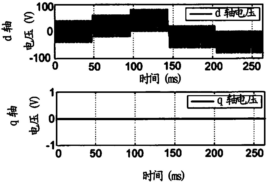
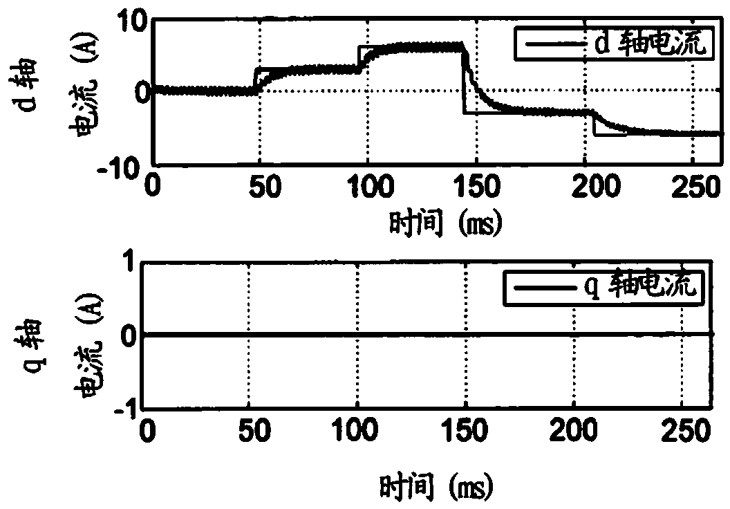
[0062] Figure 1A , 2A , 3A and 4A show the injection of voltage signals so that the magnetic saturation parameters can be determined. For each voltage signal injection, obtain the current response I on the d axis Sd , And/or get the current response I on the q axis Sq , Which allows us to determine the saturation parameters. These currents respond in Figure 1B , 2B , 3B and 4B. Use the following reasons to explain this recognition principle:
[0063] Will include the steady-state part and the high-frequency part of the voltage u s Expressed as follows:
[0064] u S = U Sd +j·u Sq among them u Sd = u - Sd + u ~ Sd · f ( Ω · t ) , u Sq = u - Sq + u ~ Sq · f ( Ω · t )
[0065] among them Represents its steady-state part (on the d axis or on the q axis), Represents its high frequency part (on the d-axis or on the q-axis), f is a periodic function and F is its centered primitive.
[0066] We thus obtain the expression:
[0067] Flux expression
[0068] ψ Sd = ψ ‾ Sd + u ~ Sd Ω · F ( Ω · t ) + O ( 1 Ω 2 ) , ψ Sq = ψ ‾ Sq + u ~ Sq Ω · F ( Ω · t ) + O ( 1 Ω 2 )
[0069] Current expression
[0070] I Sd = I - Sd + I ~ Sd · F ( Ω · t ) + O ( 1 Ω 2 ) , I Sq = I - Sq + I ~ Sq · F ( Ω · t ) + O ( 1 Ω 2 )
[0071] among them, with Represents the steady-state components of flux and torque current, and with Represents the oscillation of flux and torque current.
[0072] We obtain the first order in Ω and α (that is, by using the relation ψ Sd ≈L d ·I Sd And ψ Sq ≈L q ·I Sq ):
[0073] Ω · I ~ Sd = u ~ Sd L d + 6 · α 3,0 · L d · I ‾ Sd · u ~ Sd + 2 · α 1,2 · L q · I ‾ Sq · u ~ Sq + 2 · α 2,2 · L q · I ‾ Sq · ( 2 · L d · I ‾ Sd · u ~ Sq + L q · I ‾ Sq · u ~ Sd ) + 12 · α 4,0 · L d 2 · I ‾ Sd 2 · u ~ Sd
[0074] Ω · I ~ Sq = u ~ Sq L q + 2 · α 1 , 2 · ( L d · I ‾ Sd · u ~ Sq + L q · I ‾ Sq · u ~ Sd ) + 2 · α 2,2 · L d · I ‾ Sd · ( L d · I ‾ Sd · u ~ Sq + 2 · L q · I ‾ Sq · u ~ Sd ) + 12 · α 0,4 · L q 2 · I ‾ Sq 2 · u ~ Sq - - - ( 4 )
[0075] Because the current I Sd And I Sq Extract current oscillations from the measurement with So we obtain the relationship that makes it possible to calculate the saturation parameter through (4).
[0076] Figure 1A , 2A , 3A, 4A show that the current oscillations on the flux d-axis and torque q-axis can be extracted with Four specific cases of injection of voltage signals (steady state and high frequency) on the, d and q axes.
[0077] in Figure 1A In this, a steady-state voltage signal is applied to the q axis, and a high frequency voltage signal is applied to the d axis. Figure 1B The corresponding current response is shown.
[0078] in Figure 2A In this, a steady-state voltage signal is applied to the q-axis, and a high-frequency voltage signal is applied to the d-axis. Figure 2B The corresponding current response is shown.
[0079] in Figure 3A In this, a steady-state voltage signal is applied to the d axis, and a high frequency voltage signal is applied to the q axis. Figure 3B The corresponding current response is shown.
[0080] in Figure 4A In this, a steady-state voltage signal is applied to the d axis, and a high frequency voltage signal is applied to the q axis. Figure 4B The corresponding current response is shown.
[0081] Such as Figure 5A As shown in the high-frequency voltage signal can be a square wave signal. In this case, the obtained current oscillates with ( Figure 5B ) Is the form of a triangular wave signal, from which it is easy to extract the amplitude of each cycle of the injected signal.
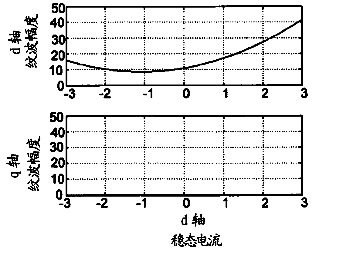
[0082] in Figure 1C , 2C In 3C and 4C, it can be seen that the amplitude of the current oscillation varies according to the obtained steady-state current level. These changes follow linear or quadratic equation relationships. Then the conventional least square method makes it possible to estimate the magnetic saturation parameter α specified above x,y.
[0083] E.g:
[0084] Adopt the system y=a·x 2 +b·x+c, where a, b, and c are the parameters to be estimated, and x and y are known signals.
[0085] Obtain the estimation of parameters a, b, and c by using the least squares formula:
[0086] · · · y k · · · = · · · · · · · · · x k 2 x k 1 · · · · · · · · · a b c ,
[0087] Which provides
[0088] a b c = inv ( · · · · · · · · · x k 2 x k 2 · · · · · · · · · T · · · · · · · · · x k 2 x k 1 · · · · · · · · · ) X · · · · · · · · · x k 2 x k 1 · · · · · · · · · T · · · y k · · · ,
[0089] or
[0090] a b c = inv ( X x k 4 X x k 3 X x k 2 X x k 3 X x k 2 X x k X x k 2 X x k X 1 ) X X x k 2 y k X x k y k X y k ,
[0091] Where (y k ,x k ) Is the measured data:
[0092] y k : For the amplitude of the current oscillation of test k,
[0093] x k : The steady-state current value for test k.
[0094] Once the magnetic saturation parameter α has been determined x,y During the normal operation of the electric motor, they can be used in the execution of the control law of the variable speed drive.
[0095] For this, such as Image 6 The control law shown in is a little different from the standard control law because it includes the treatment of the magnetic saturation of the motor.
[0096] The control law includes the reference flux current I Sd ref And reference torque current I Sq ref , According to which the reference flux voltage u is determined Sd ref And reference torque voltage u Sq ref. Reference flux voltage u Sd ref High-frequency voltage signal u is applied to it Sh , Making it possible to generate current oscillations on the flux axis d. According to the reference flux voltage u Sd ref And according to the reference torque voltage u Sq ref , The control law generates the three-phase U, V, W reference voltage u used to connect the inverter INV to the motor M U ref , U V ref , U W ref. According to reference voltage u U ref , U V ref , U W ref , The inverter generates a current I in the three phases U, V, W of the motor SU , I SV , I SW The corresponding voltage. These currents are measured and processed by the control law to convert them into flux and torque currents I Sd , I Sq , And reinject it as an input for adjustment. According to the measured flux and torque current I Sd , I Sq , The control law calculates the angular error ε corresponding to the difference between the position of the control mark (d and q axis) and the position of the rotor (ie, the rotor of the permanent magnet) (block 10). For this angular error ε, the control law adds a correction corresponding to the inclusion of magnetic saturation. Then the angle error corrected in time makes it possible to apply the gain K p And K i To evaluate the stator speed.
[0097] From a detailed point of view, when we write the motor model in the rotor mark at stop, we get:
[0098]
[0099] Where ε is the angular error between the control mark and the rotor position
[0100] I S = ( I Sd ′ + jI Sq ′ ) · e - jϵ ψ S = ( ψ Sd ′ + jψ Sq ′ ) · e - jϵ
[0101] I Sd ′ = ψ Sd ′ L d + 3 · α 3 , 0 · ψ Sd ′ 2 + α 1,2 · ψ Sq ′ 2 + 4 · α 4,0 · ψ Sd ′ 3 + 2 · α 2,2 · ψ Sd ′ ψ Sq ′ 2
[0102] I Sq ′ = ψ Sq ′ L q + 2 · α 1,2 · ψ Sd ′ ψ Sq ′ + 2 · α 2,2 · ψ Sd ′ 2 ψ Sq ′ + 4 · α 0,4 · ψ Sq ′ 3
[0103]
[0104] For the first order in ε, equation (6) becomes:
[0105] I Sd = ψ Sq L d - ψ Sq L q + 6 · α 3,0 · ψ Sd · ψ Sq - 4 · α 1,2 · ψ Sd · ψ Sq + 12 · α 4,0 · ψ Sd 2 · ψ Sq + 2 · α 2,2 · ψ Sq 3 - 6 · α 2,2 · ψ Sd 2 ψ Sq - 4 · α 0,4 · ψ Sq 3 · ϵ + ( ψ Sd L d + 3 · α 3,0 · ψ Sd 2 + α 1 , 2 · ψ Sq 2 + 4 · α 4,0 · ψ Sd 3 + 2 · α 2,2 · ψ Sd ψ Sq 2 )
[0106] I Sq = ψ Sd L d - ψ Sd L q + 3 · α 3,0 · ψ Sd 2 + 3 · α 1,2 · ψ Sq 2 - 2 · α 1,2 · ψ Sd 2 + 12 · α 0,4 · ψ Sd · ψ Sq 2 - 2 · α 2,2 · ψ Sd 3 + 6 · α 2,2 · ψ Sd ψ Sq 2 + 4 · α 4,0 · ψ Sd 3 · ϵ + ( ψ Sq L q + 2 · α 1,2 · ψ Sd ψ Sq + 4 · α 0,4 · ψ Sq 3 + 2 · α 2,2 · ψ Sd 2 ψ Sq ) - - - ( 7 )
[0107] Let us define the voltage with voltage injection on the d-axis:
[0108] u S = u ‾ Sdq + u ~ Sd · f ( Ω · t )
[0109] among them The applied voltage is controlled by the standard.
[0110] It reaches the basis of relation (5):
[0111] I S = I ‾ S + I ~ S · F ( Ω · t ) + O ( 1 Ω 2 )
[0112] ψ S = ψ ‾ S + u ~ Sd Ω · F ( Ω · t ) + O ( 1 Ω 2 ) - - - ( 8 )
[0113] among them Indicates the part corresponding to the standard control.
[0114] Now we inject the flux value (8) into the relation (7) to isolate the current oscillation to the first order. We then obtain:
[0115] I ~ Sd = ( 6 · α 3,0 · ψ Sq - 4 · α 1,2 · ψ Sq + twenty four · α 4,0 · ψ Sd · ψ Sq - 12 · α 2,2 · ψ Sd ψ Sq ) · u ~ Sd Ω · ϵ + ( 1 L d + 6 · α 3,0 · ψ Sd + 8 · α 4,0 · ψ Sd 2 + 2 · α 2,2 · ψ Sq 2 ) · u ~ Sd Ω
[0116] I ~ Sq = 1 L d - 1 L q + 6 · α 3,0 · ψ Sd - 4 · α 1,2 · ψ Sd + 12 · α 0,4 · ψ Sq 2 - 6 · α 2,2 · ψ Sd 2 + 6 · α 2,2 · ψ Sq 2 + 12 · α 4,0 · ψ Sd 2 · u ~ Sd Ω · ϵ + ( 2 · α 1,2 · ψ Sq + 4 · α 2,2 · ψ Sd ψ Sq ) · u ~ Sd Ω - - - ( 9 )
[0117] In the case of magnetic saturation, there is no current injection on the flux axis d, and the angular error ε can be expressed as a function of current oscillation and correction, where the correction makes it possible to optimize the generated torque. We then obtain:
[0118] I ~ Sq = 1 L · u ~ Sd Ω · ϵ + I ~ SqOffset - - - ( 10 )
[0119] among them
[0120] 1 L = 1 L d - 1 L q + ( 6 · α 3,0 - 4 · α 1,2 ) · L d · I Sd + ( 12 · α 0,4 + 6 · α 2,2 ) · L q 2 · I Sq 2 + ( 12 · α 4,0 - 6 · α 2,2 ) · L d 2 · I Sd 2
[0121] I ~ SqOffset = ( 2 · α 1,2 + 4 · α 2,2 · L d · I Sd ) · L q · I Sq · u ~ Sd Ω
[0122] Thus the relation (10) can be rewritten as follows:
[0123] L · Ω · I ~ Sq u ~ Sd = ϵ + L · Ω · I ~ SqOffset u ~ Sd = ϵ + ϵ Offset
[0124] Where ε Offset Corresponding to the correction of the angle error to be considered in the case of the magnetic saturation of the motor, this correction is the magnetic saturation parameter and α 1,2 The alpha 2,2 function. It is interesting to note that knowledge of these two parameters alone is sufficient to determine the correction to be applied. Therefore, the identification principle of the above parameters may be limited to these parameters.
[0125] in Image 6 , It can be seen that the determined correction ε Offset Inject directly into the angle error ε, or as a correction reference flux current I Sd ref And reference torque current I Sq ref The input is applied. The control law structure makes it possible to adjust the angle error ε to zero even in the case of the magnetic saturation of the motor.
[0126] The torque obtained from the torque current and the angle ε is When the angle ε is zero, the current consumed to provide a given torque is the smallest.

PUM

no PUM

Description & Claims & Application Information

We can also present the details of the Description, Claims and Application information to help users get a comprehensive understanding of the technical details of the patent, such as background art, summary of invention, brief description of drawings, description of embodiments, and other original content. On the other hand, users can also determine the specific scope of protection of the technology through the list of claims; as well as understand the changes in the life cycle of the technology with the presentation of the patent timeline. Login to view more.
Why Eureka
Try Eureka