Acoustic generator and acoustic generation device using same

A sound generator and speaker technology, applied in microphones, frequency/directional characteristic devices, piezoelectric/electrostrictive transducer microphones, etc., can solve the problem of generating large peaks or troughs

Active Publication Date: 2013-12-11
KYOCERA CORP
View PDF5 Cites 4 Cited by
  • Summary
  • Abstract
  • Description
  • Claims
  • Application Information

AI Technical Summary

Problems solved by technology

[0008] However, the conventional acoustic generator described above has a problem that a resonance phenomenon occurs at a specific frequency, so that a large peak or trough tends to occur in the frequency characteristics of the sound pressure.

Method used


Image

  • Acoustic generator and acoustic generation device using same
  • Acoustic generator and acoustic generation device using same
  • Acoustic generator and acoustic generation device using same

Examples


no. 1 Embodiment )

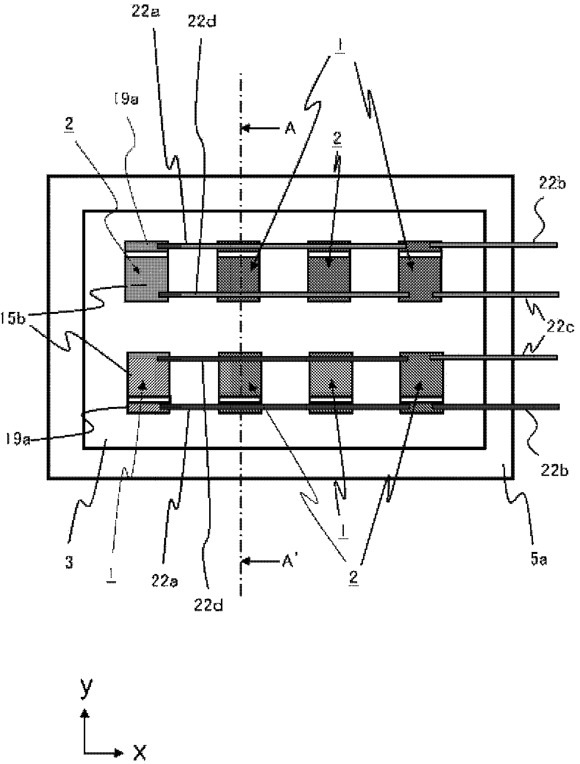
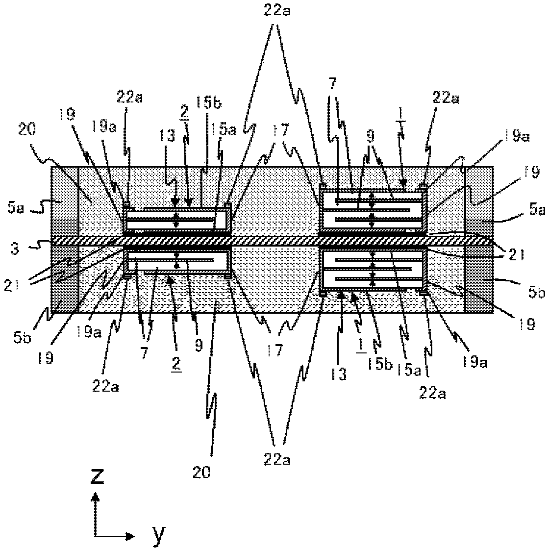
[0092] A specific example of the acoustic generator of the present invention will be described. make figure 1 , 2 The acoustic generator of the first example of the embodiment of the present invention was shown, and its electrical characteristics were measured.

[0093] First, the piezoelectric powder containing lead zirconate titanate (PZT) in which part of Zr was substituted with Sb, binder, dispersant, plasticizer, and solvent was mixed by ball milling for 24 hours to prepare a slurry . Then, using the obtained slurry, a green sheet was produced by a doctor blade method. On this green sheet, a conductor paste containing Ag and Pd as an electrode material was applied in a predetermined shape by a screen printing method. Then, the green sheet coated with the conductor paste and the green sheet not coated with the conductor paste are laminated and pressed to produce a laminated molded body. Then, this laminated molded body was degreased in the air at 500° C. for 1 hour, a...

no. 2 Embodiment )

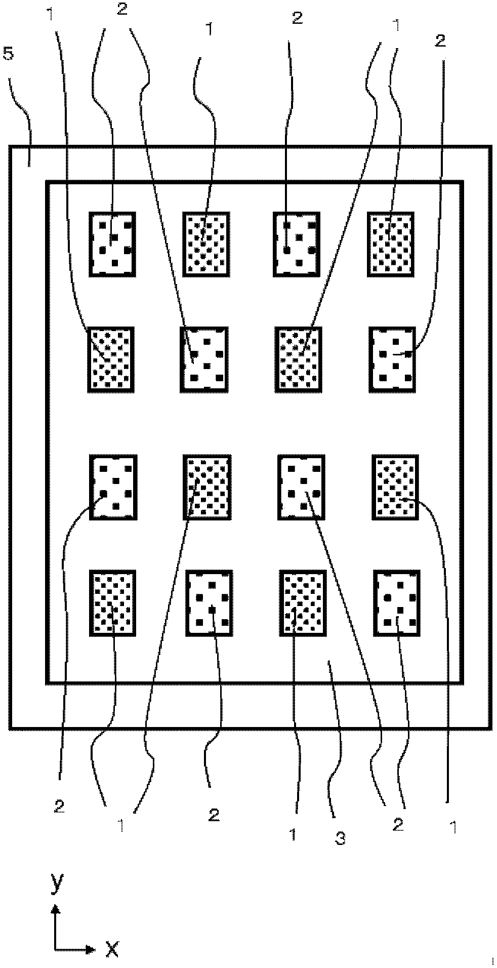
[0101] about Figure 5the acoustic generator of the fourth example of the illustrated embodiment, and Figure 9 In the acoustic generator of the second comparative example shown, the number of eigenvalues ​​of vibration (the number of vibration modes) affecting the sound pressure characteristics was calculated by simulation. in addition, Figure 5 the acoustic generator of the fourth example of the illustrated embodiment, and Figure 9 The acoustic generator of the second comparative example shown differs only in how the piezoelectric elements 1 and 2 are arranged. which is, Figure 5 In the acoustic generator of the fourth example of the illustrated embodiment, two types of acoustic generators having different thicknesses are arranged in each of two directions intersecting each other (the x-axis direction and the y-axis direction in the drawing in directions orthogonal to each other). Piezoelectric elements (Piezoelectric elements 1, 2). in comparison, Figure 9 In the ...


PUM


Abstract

To provide an acoustic generator for which peaks and dips in frequency characteristics of sound pressure are minimized, as well as an acoustic generation device using the same. This invention is an acoustic generator, and an acoustic generation device using the same, wherein the acoustic generator has at least a diaphragm, and a plurality of piezoelectric elements which are attached to the diaphragm so as to be mutually spaced apart and which vibrate the diaphragm. The plurality of piezoelectric elements comprise at least two types of piezoelectric elements (1, 2) of different thickness. In each of two mutually intersecting directions upon the main surface of the diaphragm, piezoelectric elements (1, 2) of different thickness are disposed. Accordingly, it is possible to achieve an acoustic generator, as well as an acoustic generation device, for which peaks and dips in frequency characteristics of sound pressure are minimized.

Description

technical field [0001] The present invention relates to an acoustic generator and an acoustic generator using the acoustic generator. Background technique [0002] Conventionally, an acoustic generator in which a piezoelectric element is mounted on a vibrating plate is known (for example, refer to Patent Document 1). [0003] prior art literature [0004] patent documents [0005] Patent Document 1: JP Unexamined Publication No. 2004-23436 [0006] Summary of the invention [0007] The problem to be solved by the invention [0008] However, the conventional acoustic generator described above has a problem that a resonance phenomenon occurs at a specific frequency, and a large peak or trough tends to be generated in the frequency characteristic of the sound pressure. Contents of the invention [0009] The present invention has been made in view of such problems in the prior art, and an object of the present invention is to provide a sound generator having small peaks a...

Claims


Application Information

Patent Timeline
Patent Type & Authority Applications(China)
IPC IPC(8): H04R17/00H04R1/26H04R7/04
CPCH04R17/00H04R1/26H04R17/02H04R2201/401
Inventor 福冈修一玖岛德幸二宫弘平山武山川健二
Owner KYOCERA CORP
Why Eureka
Try Eureka