
A pulsed water jet inhalation atomization device

A technology of atomization device and water jet, which is applied in the direction of injection device and liquid injection device, can solve the problems of high energy consumption and complex structure, and achieve the effects of low energy consumption, enhanced cavitation and impact ability, and obvious energy saving effect

Inactive Publication Date: 2016-03-02
CHINA UNIV OF MINING & TECH
View PDF7 Cites 0 Cited by
  • Summary
  • Abstract
  • Description
  • Claims
  • Application Information

AI Technical Summary

Problems solved by technology

Therefore, there are generally disadvantages of high energy consumption, complex structure, and high energy consumption.

Method used


Image

  • A pulsed water jet inhalation atomization device
  • A pulsed water jet inhalation atomization device

Examples


Embodiment Construction

[0010] An embodiment of the present invention will be further described below in conjunction with accompanying drawing:

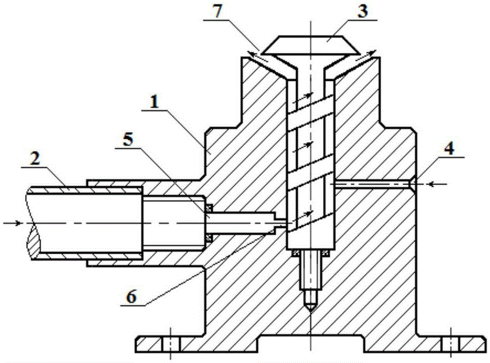
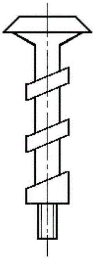
[0011] The pulse water jet inhalation atomization device of the present invention is mainly composed of a valve seat 1 , a water inlet joint 2 and a nozzle spiral column 3 . There is a central stepped blind hole in the middle of the valve seat 1, and the orifice of the central stepped blind hole is a bell mouth. The central stepped blind hole is provided with a nozzle spiral column 3 that cooperates with its inner wall to form a spiral flow channel. The nozzle spiral column 3 The tail is in the shape of a trumpet, and is matched with the trumpet mouth of the central stepped blind hole to form an annular spout 7, and the distance between the annular spouts 7 is 0.5-2mm. The spiral column 3 of the nozzle adopts a spiral groove structure, cooperates with the inner wall surface of the valve seat 1 to form a spiral flow channel, and guides the mixing of water an...


PUM


Abstract

The invention discloses a pulse water jet flow air suction atomization device, which comprises a valve seat, wherein the middle of the valve seat is provided with a center step blind hole, the hole opening of the center step blind hole is a horn opening, a spray head spiral post which is matched with the inner side wall surface of the center step blind hole for forming a spiral flow passage is arranged in the center step blind hole, the tail part of the spray head spiral post is in a horn shape and is in clearance fit with the horn opening of the center step blind hole for forming an annular spray opening, an air inlet passage and a water inlet passage communicated with a flow passage of the spray head spiral post are respectively arranged on the side wall of the valve seat, the water inlet passage is in a step shape and is positioned at the lower part of the valve seat, the air inlet passage is positioned above the opposite side of the water inlet passage, and the inlet part of the water inlet passage is provided with a water inlet joint. When water flows into a resonance cavity from the water inlet joint to reach a contraction opening, because of the barrier effect of the contraction surface, the initial pressure disturbance can be generated on the water flow, the disturbance is reflected back into the resonance cavity, and the atomization can be realized under the condition without external motive power. The pulse water jet flow air suction atomization device has the advantages that the structure is simple, the use cost is low, and the atomization effect is good.

Description

technical field [0001] The invention relates to a pulse water jet suction atomization device, which is especially suitable for water jet spray. Background technique [0002] The application range of spray technology is very wide, such as spraying, humidification, flue gas conditioning and so on. In order to achieve a good atomization effect, existing atomizers and atomization devices all need external power (such as water pumps, fans, etc.), and some also need external compressed air. Therefore, there are generally disadvantages of high energy consumption, complex structure, and high energy consumption. Contents of the invention [0003] Technical problem: The object of the present invention is to solve the problems existing in the prior art, and provide a pulsed water jet inhalation atomization device with simple structure, good atomization effect and low energy consumption. [0004] Technical solution: The pulse water jet inhalation atomization device of the present in...

Claims


Application Information

Patent Timeline
Patent Type & Authority Patents(China)
IPC IPC(8): B05B7/04
Inventor 郭楚文周家理刘霞刘雷周晓东叶鑫
Owner CHINA UNIV OF MINING & TECH
Learn More