Automatic feeding and cutting assembly line

An automatic feeding and assembly line technology, applied in shearing devices, pipe shearing devices, shearing machines, etc., can solve the problems of steel pipes crushing workers, consuming physical strength and working time, shortening working hours, improving work efficiency, Achieve the effect of fully automated operation

Inactive Publication Date: 2013-12-18
HUZHOU TIANHE MACHINERY
View PDF6 Cites 23 Cited by
  • Summary
  • Abstract
  • Description
  • Claims
  • Application Information

AI Technical Summary

Problems solved by technology

The whole work consumes a lot of physical strength and working hours, a...

Method used


Image

  • Automatic feeding and cutting assembly line
  • Automatic feeding and cutting assembly line
  • Automatic feeding and cutting assembly line

Examples


Embodiment 1

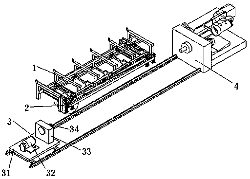
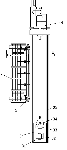
[0026] Example 1, such as Figure 1-2 As shown, a steel pipe automatic feeding and cutting line includes a storage rack 1, a material lifting device 2, a feeding device 3 and a cutting device 4;

[0027] There are 6 material storage racks 1, which are connected to each other by guide rods, and there is a certain distance between each material storage rack 1. The table top of material storage rack 1 is inclined, and the steel pipe placed on it can roll from one end to the other end, but the two ends of material storage rack 1 are all provided with ear protectors that stop the steel pipe from falling. After the material lifting device 2 lifts away a steel pipe, the adjacent second steel pipe will roll down to replace the steel pipe that has been lifted away.

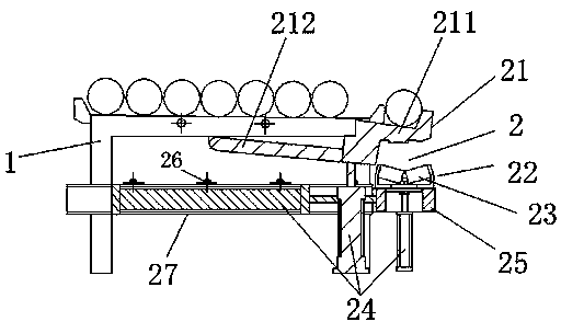
[0028] From Figure 3-5 It can be seen that the feeding device 2 includes a taking-in device 21 for extracting one steel pipe each time from the storage rack 1 and a taking-out device 22 for transporting the steel pipe i...


PUM


Abstract

The invention discloses an automatic feeding and cutting assembly line. The automatic feeding and cutting assembly line comprises a storage rack, a lifting device, a feeding device and a cutting device, wherein the lifting device comprises a get-in device for independently extracting a steel pipe from the storage rack and a get-out device for getting the steel pipe in the get-in device out and conveying to the feeding device; the get-in device comprises an extraction component, a connecting rod and a cylinder; the extraction component is hinged to the storage rack through the connecting rod and is driven by the cylinder to move up and down; the get-out device comprises a bracket frame which is arranged on the lower part of the get-in device and can move horizontally; the bracket frame is provided with a tray which moves up and down. According to the assembly line, the labor cost is greatly saved, the working efficiency is improved, fully automatic operation is realized, and the finally required length of the steel pipe is cut under control. The overall working time for cutting one steel pipe is greatly shortened, and uniform length of each steel pipe can be guaranteed at last.

Description

technical field [0001] The invention relates to the field of mechanical processing equipment, in particular to automatic operation equipment for a complete set of assembly line from steel pipe collection to cutting. Background technique [0002] Since the original embryonic steel pipes are very long, they can be cut according to the required length. In general factories, the raw steel pipes are purchased and pushed together by a crane, and then several workers lift one steel pipe to the cutting device at a time for cutting. The whole work consumes a lot of physical strength and working hours, and it is also prone to safety accidents, such as steel pipes crushing workers. Contents of the invention [0003] The purpose of the present invention is to solve the above technical problems and provide an automatic feeding and cutting line from collecting steel pipes to cutting them into finished products. [0004] The technical solution of the present invention is: an automa...

Claims


Application Information

Patent Timeline
IPC IPC(8): B23D21/00B23Q7/00
Inventor 钮树荣
Owner HUZHOU TIANHE MACHINERY
Why Eureka
Try Eureka