
Flexible tooling for milling and turning machining centers

A composite machining center and flexible tooling technology, applied in metal processing equipment, metal processing machinery parts, positioning devices, etc., can solve problems such as processing difficulties and reduce processing efficiency, and achieve the effects of improving processing efficiency, saving time, and facilitating processing

Active Publication Date: 2015-08-19
HARBIN TURBINE +1
View PDF6 Cites 0 Cited by
  • Summary
  • Abstract
  • Description
  • Claims
  • Application Information

AI Technical Summary

Problems solved by technology

[0004] The purpose of the present invention is to provide a flexible tooling of a milling and turning compound machining center to solve the problem of using DMG machine tools to process larger or smaller workpieces to be processed, or to process many workpieces to be processed that need to be arranged on the workbench. It brings difficulties to processing and reduces the processing efficiency

Method used


Image

  • Flexible tooling for milling and turning machining centers
  • Flexible tooling for milling and turning machining centers
  • Flexible tooling for milling and turning machining centers

Examples


specific Embodiment approach 1

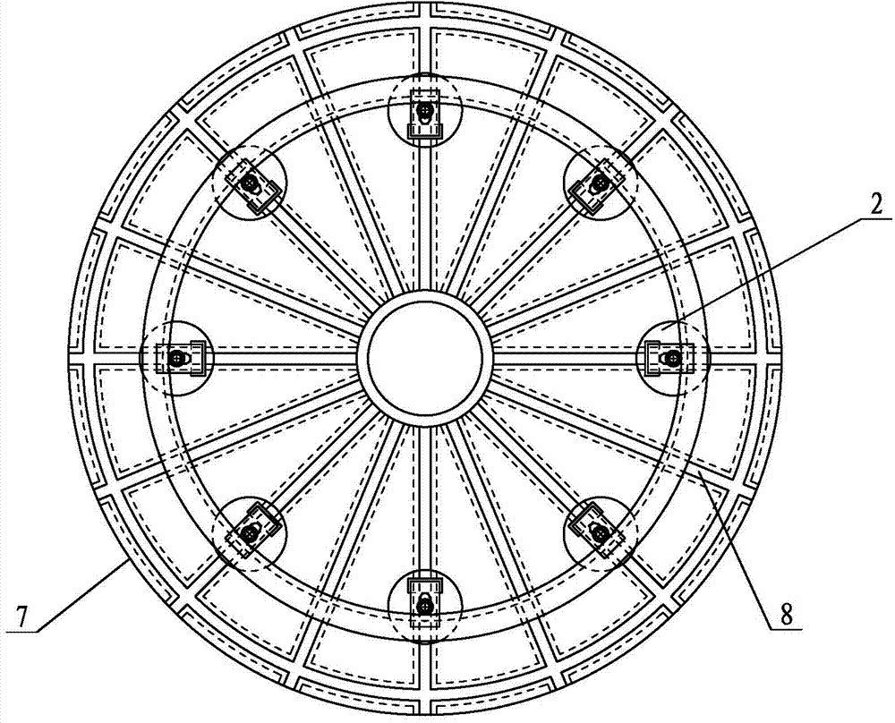
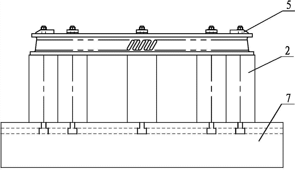
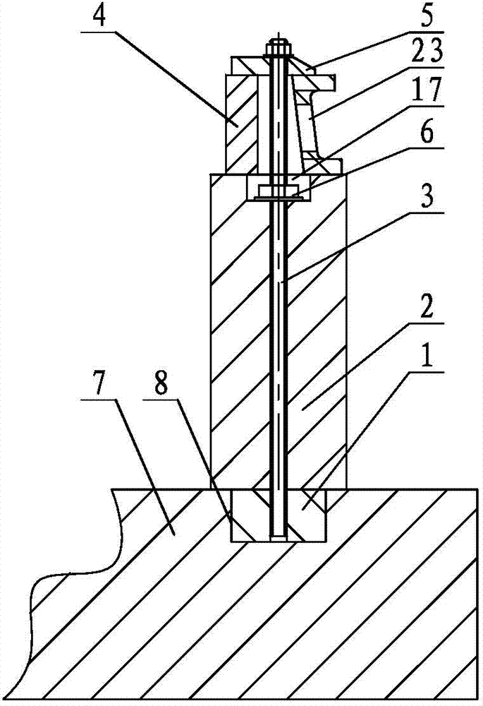
[0012] Specific implementation mode one: combine Figure 1 ~ Figure 3 and Image 6 with Figure 7 Explain, the flexible tooling of the milling-turning compound machining center in this embodiment, the flexible tooling of the milling-turning compound machining center includes at least two T-shaped blocks 1, at least two cylinders 2, at least two screws 3, and at least two pads 4. At least two pressure plates 5 and at least four nuts 6; the at least two T-shaped blocks 1, at least two cylinders 2, at least two screws 3, at least two pads 4 and at least two pressure plates 5 The numbers are all the same, the number of nuts 6 is twice the number of screw rods 3, and the at least two T-shaped blocks 1 are set upside down in the inverted T-shaped chute 8 of the machine tool workbench 7, and the T-shaped blocks set upside down 1 is matched with the inverted T-shaped chute 8 of the machine tool table 7, and a cylinder 2 is erected on the upper surface of each inverted T-shaped block...

specific Embodiment approach 2

[0013] Specific implementation mode two: combination figure 1 , Image 6 with Figure 7 Note that the number of cylinders 2 in this embodiment is two to eight. Select according to the size of the outer diameter of the workpiece 23 to be processed. The undisclosed technical features in this embodiment are the same as those in the first embodiment.

specific Embodiment approach 3

[0014] Specific implementation mode three: combination Figure 4 with Figure 5 Explain that the flexible tooling of the milling and turning compound machining center in this embodiment includes a faceplate 9, at least two nuts one 10, at least two T-shaped blocks one 11, at least two T-shaped blocks two 12, and at least two pressure plates one 13 , at least two pressure plates 14, at least two pads 15, at least two pads 16, at least two cylinders 2, at least two screw rods 18, at least two screw rods 19 and at least four nuts two 20;

[0015]The quantity of described at least two pressing plates one 13, at least two pads one 15, at least two screw rods two 19, at least two cylinders 2 and at least two T-shaped blocks one 11 is all the same, and the at least two pressing plates Two 14, at least two pads two 16, at least two screw rods two 19 and at least two T-shaped blocks two 12 have the same quantity, the number of nut one 10 is twice the number of screw rod one 18, and t...


PUM


Abstract

The invention discloses a flexible tool of a vehicle milling combined machining center, which relates to a tool for vehicle milling machining and solves the problems that due to the adoption of a DMG (Deckel Maho Gildemeister) machine tool for machining a to-be-machined workpiece in larger or smaller size or multiple to-be-machined workpieces needing to be arranged on a working platform, the machining is difficult, and the machining efficiency is reduced. The flexible tool adopts the following schemes that scheme I: a T-shaped block is inversely arranged in an inversed T-shaped sliding chute of a machine tool working platform, the T-shaped block which is inversely arranged is provided with a cylindrical body, the lower end of a screw rod penetrates into a through hole of the cylindrical body and a screw hole in the T-shaped block which is inversely arranged, the lower end of the screw rod is in threaded connection with two nuts, the upper surface of the cylindrical body is provided with a cushion block, one end of a pressing plate is arranged on the cushion block, and the upper end of the screw rod penetrates out of a through hole on the pressing plate; scheme II is different from the scheme I in a way that a disk chuck is arranged on the machine tool working platform, and the cylindrical body is arranged on the disk chuck. According to the flexible tool disclosed by the invention, multiple to-be-machined workpieces can be clamped and fixed, the machining efficiency is increased, and all machining of the machine tool on vehicle milling, drilling, boring and oil filler hole inclining of the to-be-machined workpieces is realized.

Description

technical field [0001] The invention relates to a tooling for milling and turning. Background technique [0002] With the development of the international steam turbine business, the requirements of the steam turbine factory on machine tools are becoming more and more stringent. The milling and turning center DMU125FDduoBLOCK of the well-known German machine tool company DMG Group has been applied to the production and machining of steam turbines. The application of DMG machine tools in steam turbine processing can complete the turning, drilling, boring, and inclined oil injection holes of batches of large workpieces to be processed in one clamping. [0003] Since the lowest point of the tool center is only 300mm away from the surface of the table when the DMG machine tool spindle moves horizontally, for workpieces to be processed that are not higher than 300mm, the workpiece to be processed can only be realized by placing a large plate under the workpiece to be processed. ...

Claims


Application Information

Patent Timeline
Patent Type & Authority Patents(China)
IPC IPC(8): B23Q3/06
Inventor 董礼涛张涛车延超高伟杨庆仁王丽红温东升齐孙岩李军王占军何志国
Owner HARBIN TURBINE
Learn More