Antisplash oil inlet mechanism

An anti-splash and oil intake technology, used in mechanical equipment, engine components, machines/engines, etc., can solve the problem that the oil pump is susceptible to fuel shock, and achieve the effects of improving adhesion resistance, prolonging service life and reducing conveying resistance.

Inactive Publication Date: 2013-12-18
成都陵川车用油箱有限公司
View PDF5 Cites 0 Cited by
  • Summary
  • Abstract
  • Description
  • Claims
  • Application Information

AI Technical Summary

Problems solved by technology

[0004] The invention provides an anti-splash oil inlet mechanism, which solves the problem that the oil pump is vulnerable to fuel impact, so as to achieve the purpose of protecting the oil pump and improving the service life of the oil pump

Method used


Image

  • Antisplash oil inlet mechanism
  • Antisplash oil inlet mechanism

Examples


Embodiment 1

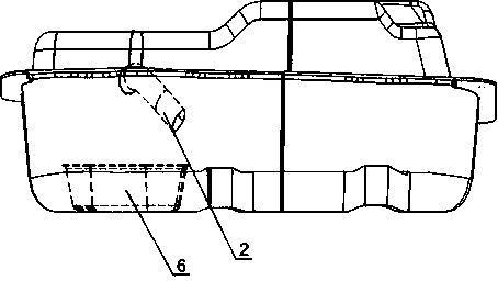
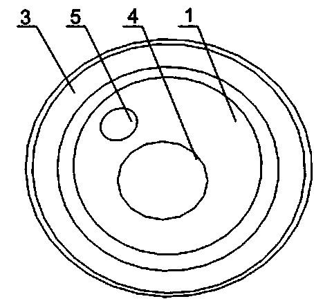
[0020] Such as figure 1 As shown, this embodiment includes an oil guide pipe and an oil suction groove 6, the end of the oil guide pipe is placed in the oil suction groove 6, the oil guide pipe includes an oil pipe 2 and an oil outlet 3, and a spacer 1 is installed in the oil outlet 3, and the spacer 1 Placed at the junction of the oil outlet 3 and the oil pipe 2, the spacer 1 is provided with an oil outlet 4 and an adjustment hole 5, the oil outlet 4 is flanged to the side close to the oil pipe 2, and the oil pipe 2 is arc-shaped. There is an oil suction groove 6 in the fuel tank, and the oil inlet 3 of the fuel pump is placed in the oil suction groove 6. The fuel flows into the oil suction groove 6 quickly through the oil guide pipe. There is a certain impact between the groove 6 and the oil inlet of the fuel pump; the spacer 1 installed in the oil outlet 3 can play the role of buffering the rapid flow of fuel and impacting the oil outlet 3 and the fuel pump inlet, and the o...

Embodiment 2

[0022] Such as figure 1 As shown, on the basis of Embodiment 1, this embodiment also includes a coating arranged on the inner wall of the spacer 1 and the oil pipe 2. The fuel oil impacts the inner wall of the spacer 1 or the oil pipe 2 for a long time, and the spacer 1 or The inner wall of oil pipe 2 is easy to be damaged. Installing a coating on the inner wall of spacer 1 or oil pipe 2 can greatly increase the delivery volume or reduce the pressure of oil pipe 2, or reduce the attachment of spacer 1 to ensure smooth passage of fuel. Increase economic benefits.

[0023] As preferably, the coating is a mixture of solvent-free modified epoxy resin and ceramic microbeads and a mixture of ceramic microbeads, solvent-free modified epoxy resin is used as the film-forming substance of the coating, and ceramic microbeads are used as fillers, which can effectively Improve the anti-adhesion of the coating, improve the smoothness of the inner wall of the oil pipe 2, reduce the conveyin...


PUM


Abstract

The invention discloses an antisplash oil inlet mechanism, comprising an oil pipe and an oil outlet, wherein a separate slice is installed in the oil outlet; an internal thread is formed in the inner wall of the oil outlet; the separate slice is arranged at the connection part of the oil outlet and the oil pipe; an oil outlet hole and an adjusting hole are formed in the separate slice; the oil outlet hole is flanged towards one side close to the oil pipe. The separate slice between the oil outlet and the oil pipe can enable the speed of fast flowing fuel oil to be slowed down, so that the fuel oil enters a fuel oil pump through the oil outlet hole; therefore, the fuel oil is prevented from entering an oil inlet port through along the inner wall of the oil pipe, and the splash is reduced; the adjusting hole can implement adjustment in the case of great fuel oil amount; as a part of fuel oil is enabled to flow out through the adjusting hole, the decompression is realized; since one side close to the oil pipe, of the oil outlet hole is flanged, the fuel oil slowly forms an inclination angle due to self-inertia; an oil column formed by the fuel oil flowing through the oil outlet hole within a certain distance gradually becomes small, so that outward splash and expansion cannot be caused and the anti-splash effect is enhanced.

Description

technical field [0001] The invention relates to fuel delivery equipment, in particular to an anti-splash fuel inlet mechanism. Background technique [0002] The function of the fuel supply system is to supply the fuel required by the fuel under various working conditions to the engine in a timely manner. Device, fuel injector, oil delivery pipe, cold start fuel injector, etc. The fuel is pumped out of the fuel tank by the fuel pump, filtered out by the fuel filter, and sent to the fuel pressure regulator through the oil pressure pulse damper. Under the action of the fuel pressure regulator, the difference between the oil pressure and the air pressure in the intake pipe The difference is kept constant and then distributed by the fuel delivery lines to the individual injectors and cold start injectors. According to the instructions of ECU, the fuel injector controls the fuel injection start time and fuel injection duration of the fuel injector, so that the fuel injector can...

Claims


Application Information

Patent Timeline
IPC IPC(8): F02M37/00
Inventor 冯克武詹和锋王勇荣长江黎林王先锋余正秀刘坤学
Owner 成都陵川车用油箱有限公司
Why Eureka
Try Eureka