
A multi-way hydraulic control valve

A technology of hydraulic control valves and hydraulic valves, which is applied in the direction of fluid pressure actuators, servo motor components, mechanical equipment, etc., can solve the problems of unstable equipment performance, low safety factor, and low cost, and achieve industrial automation, The effect of low cost and stable performance

Active Publication Date: 2015-10-28
冯广建
View PDF6 Cites 0 Cited by
  • Summary
  • Abstract
  • Description
  • Claims
  • Application Information

AI Technical Summary

Problems solved by technology

In the existing automation equipment, numerical control or relays are generally used to realize automatic control. Among them, the numerical control automation equipment has the advantages of convenient operation, stable performance and high efficiency, but the cost of the existing numerical control equipment is generally tens of times higher than that of ordinary equipment. times, there are disadvantages of high cost and difficult maintenance; and the equipment that uses relays to realize automation has low cost, high efficiency, and is easy to replace and maintain, but because the relay is prone to failure, the performance of the equipment is unstable and safe. The coefficient is also lower

Method used


Image

  • A multi-way hydraulic control valve
  • A multi-way hydraulic control valve
  • A multi-way hydraulic control valve

Examples


Embodiment Construction

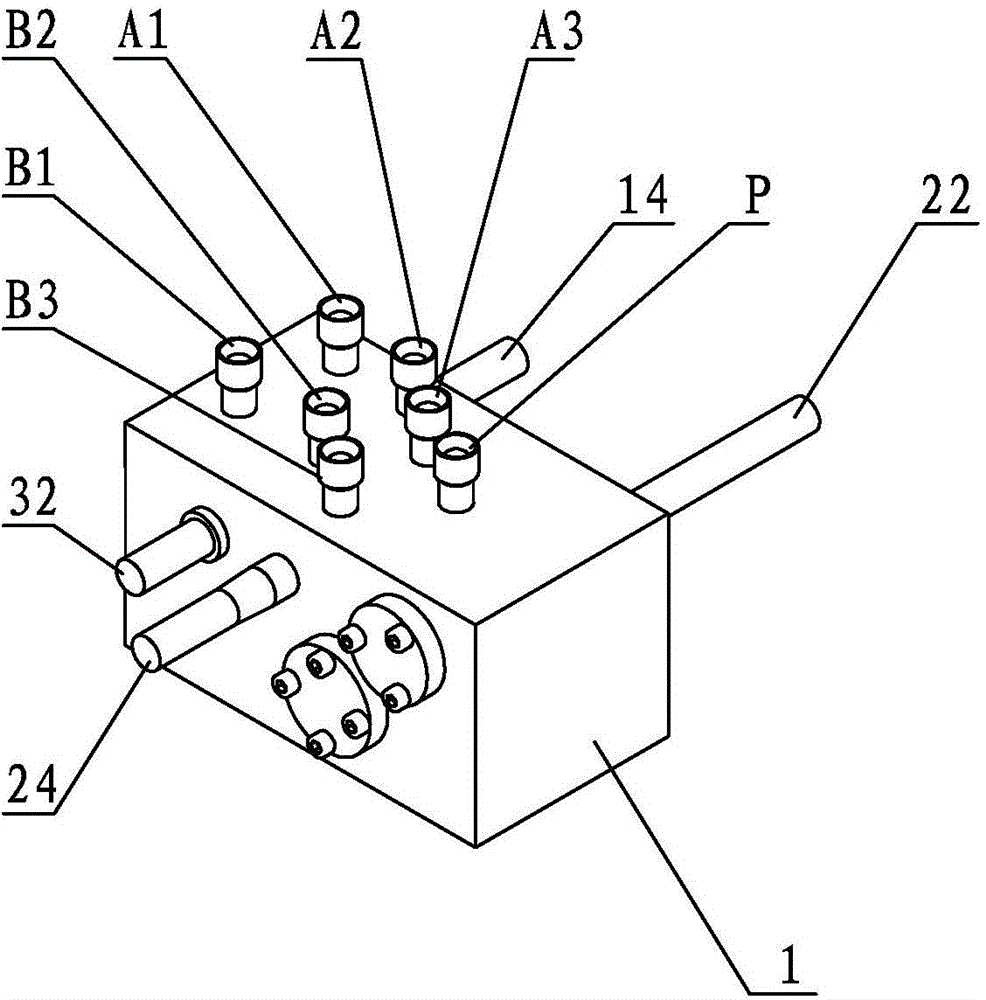
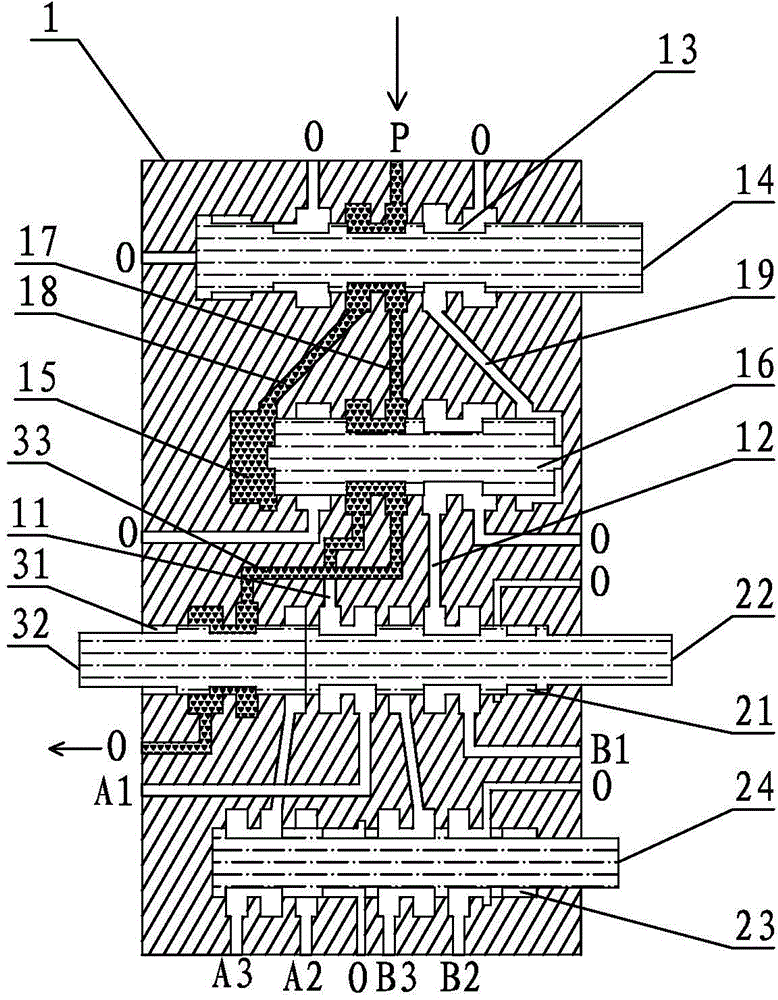
[0031] The multi-way hydraulic control valve of the present invention will be further described in detail below with reference to the accompanying drawings and preferred embodiments.

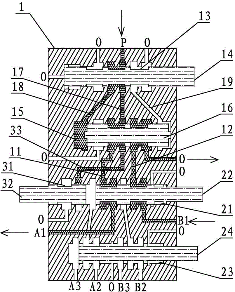
[0032] refer to figure 1 , figure 2 , one of the preferred embodiments of the present invention, includes a valve body 1, a reversing valve group and a switching valve group are arranged in the valve body 1, and the reversing valve group and the switching valve group pass through the first connecting oil passage 11 and the second connecting oil passage. Road 12 is connected.

[0033] The reversing valve group includes a reversing groove 13 and a hydraulic valve groove 15, and the reversing groove 13 is connected to the hydraulic valve groove 15 through the oil inlet oil passage 17, the left hydraulic oil passage 18 and the right hydraulic oil passage 19, wherein The left hydraulic oil passage 18 and the right hydraulic oil passage 19 are respectively connected to the left and right ends of th...


PUM


Abstract

The invention discloses a multi-channel hydraulic control valve which comprises a valve body, wherein a reversing valve group and a change-over valve group are arranged in the valve body; the reversing valve group is connected with the change-over valve group through a first connecting oil passage and a second connecting oil passage; a reversing valve core in the reversing valve group acts to enable the first connecting oil passage and the second connecting oil passage to be in switching connection between an oil inlet and respective oil unloading openings respectively; a plurality of groups of oil cylinder connecting openings are formed in the change-over valve group, and change-over valve cores used for switching the oil cylinder connecting openings which are communicated with the first connecting oil passage and the second connecting oil passage are arranged on the change-over valve group. The multi-channel hydraulic control valve disclosed by the invention completely adopts a mechanical mechanism to realize the control to hydraulic oil channels, has the advantages of simple structure, low cost, stability in performance of mechanical valves and convenience for maintenance, is used for steering control of oil cylinder pistons and switching control of oil cylinders in a multi-channel hydraulic power system, facilitates the realization of automation control, and has a wide application prospect.

Description

technical field [0001] The invention relates to a control valve, in particular to a multi-channel hydraulic control valve. Background technique [0002] In modern times, industrial automation has been widely used in production, and some production equipment has realized fully automatic or semi-automatic operation, which saves labor and improves production efficiency. In the existing automation equipment, numerical control or relays are generally used to realize automatic control. Among them, the numerical control automation equipment has the advantages of convenient operation, stable performance and high efficiency, but the cost of the existing numerical control equipment is generally tens of times higher than that of ordinary equipment. times, there are disadvantages of high cost and difficult maintenance; and the equipment that uses relays to realize automation has low cost, high efficiency, and is easy to replace and maintain, but because the relay is prone to failure, th...

Claims


Application Information

Patent Timeline
Patent Type & Authority Patents(China)
IPC IPC(8): F15B13/02
Inventor 冯广建
Owner 冯广建
Learn More