Energy-concentrating gas-saving infrared generator for gas appliances

A technology for generators and gas appliances, which is applied in the direction of burners, combustion methods, and combustion types. Effect of heat loss and improvement of safety performance

Active Publication Date: 2016-01-20
WUXI SHENGHE TECH
View PDF6 Cites 0 Cited by
  • Summary
  • Abstract
  • Description
  • Claims
  • Application Information

AI Technical Summary

Problems solved by technology

However, the addition of other devices will cause problems in manufacturing, assembly and production technology, complicate the manufacturing process, and increase the scrap rate of finished products. At the same time, because the thermal expansion coefficients of different materials are different, it is easy to cause problems such as falling off and separation after long-term use, thus affecting the service life and quality. safe to use

Method used


Image

  • Energy-concentrating gas-saving infrared generator for gas appliances
  • Energy-concentrating gas-saving infrared generator for gas appliances
  • Energy-concentrating gas-saving infrared generator for gas appliances

Examples


Embodiment Construction

[0032] The specific implementation manner of the present invention will be described below in conjunction with the accompanying drawings.

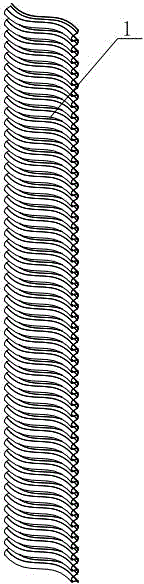
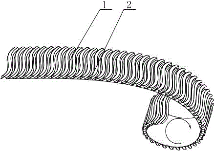
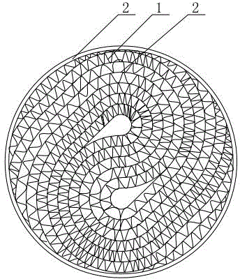
[0033] Such as figure 1 , figure 2 , image 3 , Figure 4 , Figure 5 , Figure 6 and Figure 7 As shown, the energy-gathering and gas-saving infrared generating body for gas appliances in this embodiment includes a long metal strip, and the long metal strip is divided into a corrugated belt 1 and a flat belt 2. The corrugated belt 1 and the flat belt 2 overlap each other and are wound or stacked in parallel to form In the infrared generating body, a pipeline through which gas passes is formed between the convex embossing on the surface of the corrugated belt 1 and the plane of the flat belt 2 . The pipeline is a bent structure, which is a curved through hole.

[0034] Such as figure 1 As shown, the transverse section and the longitudinal section of the corrugated zone 1 both form a regular wavy structure.

[0035] Such as Figu...


PUM


Abstract

The invention relates to an energy-gathering gas-saving infrared generator for gas appliances. The energy-gathering gas-saving infrared generator comprises a long metal strip divided into a wave strip and a flat strip, the wave strip and the flat strip are interlapped and then coiled or parallelly stacked to form the infrared generator, and a gas passing pipeline is formed between convex embossed stripes on the surface of the wave strip and a plane of the flat strip. Through structural change of the wave strip, the wave strip can be of a wavy structure or bent structure, complexity of manufacture and assembly technology is lowered, materials are saved, unstable factors during manufacture and use are decreased, and safety performance of products is greatly improved.

Description

technical field [0001] The invention relates to the technical field of auxiliary equipment for gas appliances, in particular to an energy-gathering and gas-saving infrared generator for gas appliances. Background technique [0002] At present, nearly half of the gas is wasted in ordinary gas furnaces. There are two main reasons for the waste of gas: (1) Insufficient combustion of gas, that is, "chemical heat loss", and the unburned gas is directly wasted; ( 2) Existing gas appliances rely on the flame to transfer heat to the bottom of the pot through convection, but the contact between the flame and the bottom of the pot is only a moment, and a large amount of heat is dissipated into the air without being used. This is called "thermophysical transfer loss." ". Therefore, the thermal efficiency of the atmospheric gas furnace is usually only 55%, and nearly half of the gas is wasted. [0003] In the prior art, the solution usually adopted is to convert the heat energy genera...

Claims


Application Information

Patent Timeline
Patent Type & Authority Patents(China)
IPC IPC(8): F23D14/46F23D14/14
Inventor 吴昌文
Owner WUXI SHENGHE TECH
Why Eureka
Try Eureka