

Non-steady flow simulating method for pipe network system
A non-constant flow, analog method technology, applied in instruments, computing, electrical and digital data processing, etc., can solve the problem of low simulation accuracy, and achieve the effect of simple coding, fast calculation speed, and simplified calculation complexity
- Summary
- Abstract
- Description
- Claims
- Application Information
AI Technical Summary
Problems solved by technology
Method used
Image

Examples
Embodiment 1
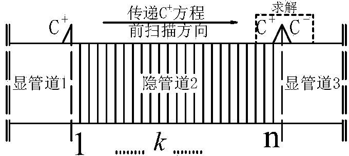
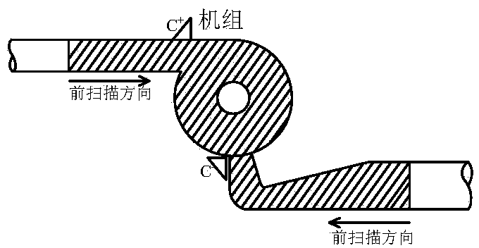
[0132] In the piping system, non-prismatic pipes are solved by implicit difference method and other pipes are solved by explicit difference method.
[0133] The draft tube is a non-prismatic pipe, and its pressure value is an important adjustment parameter in the transition process of the hydropower station. The draft tube is a flow passage with variable cross-section. Excessive negative pressure in the draft tube of the hydropower station will lead to the instability of the steel lining. , water column separation and other unfavorable phenomena, too low pressure may also lead to the release of gas in the water body, and the resulting impact pressure will cause cavitation and vibration of the turbine runner. The flow and moment characteristics of the turbine are generally determined by the comprehensive characteristic curve of the runner model under stable conditions. These characteristic curves do not include the influence of the inertia of the water flow under the unstable co...
Embodiment 2
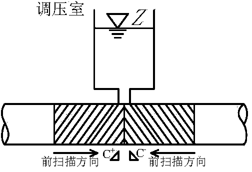
[0135] In the piping system, the surge chamber is solved by the implicit difference method, and the other pipes are solved by the explicit difference method.
[0136] Using the method of the present invention to solve the surge in the surge chamber mainly includes two steps: the first step is to jointly solve the problem by using the explicit difference method and the implicit difference method; the second step is to use the implicit dynamic grid to track the free water surface of the surge chamber.
[0137] See Figure 10 The surge chamber and pipeline shown in the figure, the upstream and downstream pipelines of the surge chamber are solved by the characteristic line method, and the surge chamber is solved by using the Preissmann four-point implicit scheme after discretization.
[0138] The surge chamber is divided into n sections, and the end section n is the free water surface. In the case of grid determination, the water head H n It is known that the supplementary equat...
Embodiment 3
[0157] In the pipeline system, the implicit scheme difference method is used to solve the pipeline with full flow, and the explicit scheme difference method is used to solve the pipeline with subflow.
[0158] The basic equations of unsteady flow in open channels can be solved using explicit and implicit difference schemes. The explicit difference scheme is mainly the characteristic line method. First, the solution must satisfy the Courant condition, the time step is limited, and the numerical stability is difficult to guarantee ; Second, interpolation is required, and interpolation errors are unavoidable, especially when the transient process is intense, and special care must be taken when using this calculation method, as errors may sometimes overwhelm the actual results. Therefore, the display differential format is generally less used in bright full-flow calculations.
[0159] for Figure 12 As shown in the hydropower station with a diversion tunnel combined with a tailra...
PUM
 Abstract
Description
Claims
Application Information