Check patentability & draft patents in minutes with Patsnap Eureka AI!

Transconductance amplifier and LED constant current drive circuit

A transconductance amplifier and circuit technology, applied in the field of transconductance amplifiers, can solve problems such as increased circuit offset, enlarged symmetrical component size, symmetrical input tube symmetrical resistance and mirror current mismatch, and achieves the effect of improving consistency

Active Publication Date: 2013-12-18
HANGZHOU SILAN MICROELECTRONICS
View PDF5 Cites 6 Cited by
  • Summary
  • Abstract
  • Description
  • Claims
  • Application Information

AI Technical Summary

Problems solved by technology

However, due to the deviation in the manufacturing process and packaging stress, the designed symmetrical input tube, symmetrical resistance and mirror current will become mismatched, which will cause the transconductance of the actual circuit to be no longer accurate, and the offset of the circuit will increase significantly.
In order to reduce this mismatch, it is generally necessary to make all components that cause mismatch as symmetrical as possible, including the central symmetry of the layout, and increase the size of the symmetrical components, but this will result in a larger chip area. This increases the cost of matching
In addition, even with these measures, the problem caused by mismatch is still not well solved, especially the mismatch is affected by the stress of the package, and the effect of increasing the size of the symmetrical component is not obvious

Method used


Image

  • Transconductance amplifier and LED constant current drive circuit
  • Transconductance amplifier and LED constant current drive circuit
  • Transconductance amplifier and LED constant current drive circuit

Examples


Embodiment Construction

[0059] The present invention will be further described below in conjunction with specific embodiments and accompanying drawings, but the protection scope of the present invention should not be limited thereby.

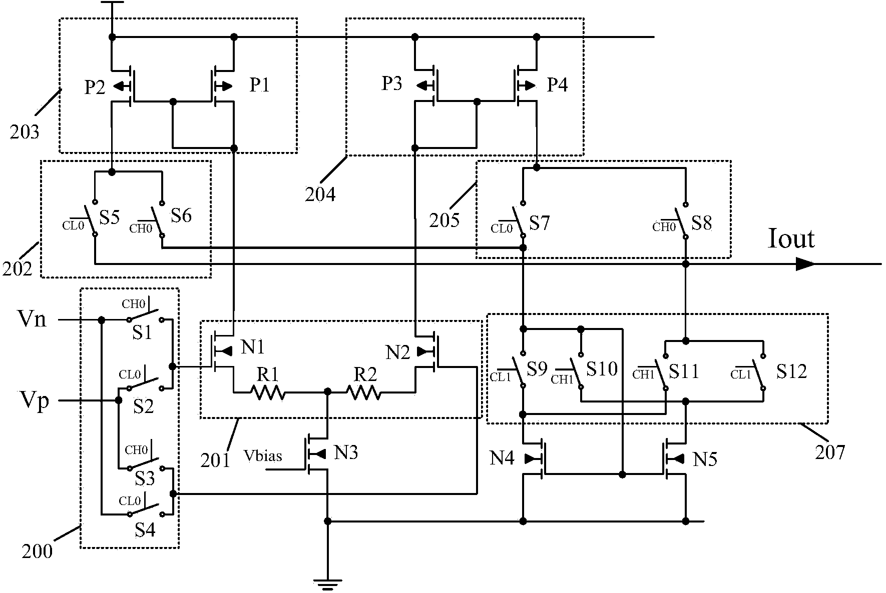
[0060] refer to image 3 , the transconductance amplifier of this embodiment includes: an input switch network 200, a differential input stage circuit 201, a current transfer circuit, a current transfer switch network and a clock signal generator.

[0061] Further, the differential input stage circuit 201 includes a first voltage-to-current circuit and a second voltage-to-current circuit. In this embodiment, the first voltage-to-current circuit includes a first differential input pair transistor N1 and a first resistor R1 connected in series with it, and the second voltage-to-current circuit includes a second differential input pair transistor N2 and a second resistor connected in series with it R2, the differential input stage circuit 201 is connected to the ground v...


PUM


Abstract

The invention provides a transconductance amplifier and an LED constant current drive circuit. The transconductance amplifier comprises a differential input stage circuit, a current transmitting circuit, an input switching network, a current transmitting switching network and a clock signal generator. The differential input stage circuit comprises a first voltage-to-current circuit and a second voltage-to-current circuit; the current transmitting circuit carries out transmission on currents output by the differential input stage circuit; the input switching network carries out switching on input positive input signals and input negative input signals, and thus the input positive input signals and the input negative input signals are made to be input to the input end of the first voltage-to-current circuit and the input end of the second voltage-to-current circuit alternatively; the current transmitting switching network carries out switching on the current transmitting paths of the current transmitting circuit, and thus output signals of the transconductance amplifier are made to be maintained in positive polarity with positive input signals and to be maintained in reversed polarity with negative input signals; the clock signal generator generates first clock signals, second clock signals, third clock signals and fourth clock signals, wherein the first clock signals, the second clock signals, the third clock signals and the fourth clock signals are non-overlapped signals in periodicity, the first cock signals are in phase reversal with the second clock signals, and the third clock signals are in phase reversal with the fourth clock signals. The transconductance amplifier and the LED constant current drive circuit can reduce detuning caused by matching of devices and packaging stress, and are beneficial to improving the conformance of circuits.

Description

technical field [0001] The invention relates to the technical field of transconductance amplifiers, in particular to a transconductance amplifier and an LED constant current drive circuit. Background technique [0002] refer to figure 1 , the traditional step-down LED driving circuit mainly includes: a constant current control circuit 100, a freewheeling diode D1, an inductor L1, a capacitor C1, a switch tube M1, and a sampling resistor Rcs. Wherein, the negative pole of the freewheeling diode D1 is connected to the positive pole of the load LED and the power supply terminal Vin, the positive pole of the freewheeling diode D1 is connected to the first terminal of the inductor L1, and the second terminal of the inductor L1 is connected to the negative pole of the load LED; the switching tube M1 Connected between the inductor L1 and the sampling resistor Rcs, the switch tube M1 is controlled by the constant current control circuit 100 . [0003] Wherein, the constant current...

Claims


Application Information

Patent Timeline
Patent Type & Authority Applications(China)
IPC IPC(8): H05B37/02
CPCY02B20/40
Inventor 姚云龙吴建兴
Owner HANGZHOU SILAN MICROELECTRONICS
Features
  • R&D
  • Intellectual Property
  • Life Sciences
  • Materials
  • Tech Scout
  • Unparalleled Data Quality
  • Higher Quality Content
  • 60% Fewer Hallucinations
Learn More