Arrangement in wire feeding device of welding machine and method for moving welding wire

A technology of supplying device and welding machine, which is applied in welding equipment, transportation and packaging, arc welding equipment, etc., can solve the problems of difficulty in uniform supply of welding wire, etc.

Active Publication Date: 2013-12-18
KEMPPI OY
View PDF10 Cites 4 Cited by
  • Summary
  • Abstract
  • Description
  • Claims
  • Application Information

AI Technical Summary

Problems solved by technology

In some cases, during the welding process, it is also possible to use a double pulse method, where electrical and mechanical pulses are used alternately, where the wire feed speed has to vary with respect to time, which further increases the difficulty of uniform feeding of the wire

Method used


Image

  • Arrangement in wire feeding device of welding machine and method for moving welding wire
  • Arrangement in wire feeding device of welding machine and method for moving welding wire

Examples


Embodiment Construction

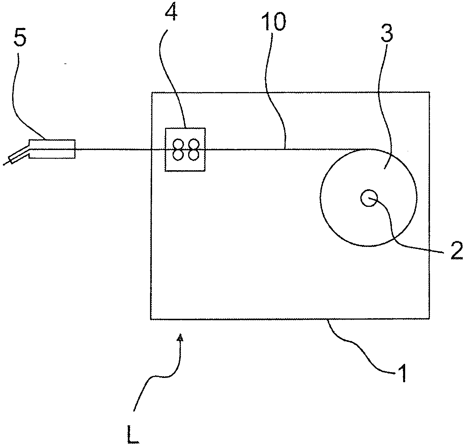
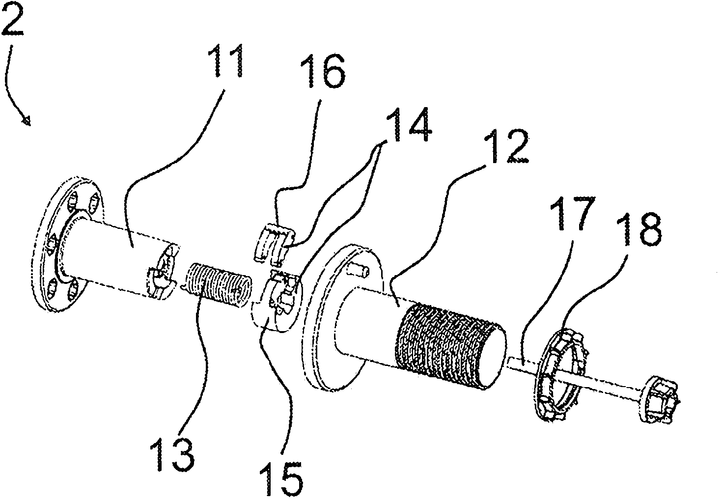
[0030] figure 1 A wire feeding device L is shown, which in this example is itself an overall device. The welding wire feeding device L can be positioned in relation to the power source, in relation to the welding torch or as a combined device, the welding wire feeding device L described in the claims is not limited to one of these alternatives, but it can be positioned in the claims vary within the required range. The welding wire supply device L comprises a frame 1 and a hub system 2 arranged in the frame, in association with which a welding wire reel 3 is arranged. The welding wire coil 3 comprises a welding wire 10 which is unwound from the welding wire coil 3 by means of a welding wire supply mechanism 4 and fed by the welding wire supply mechanism 4 to a welding torch 5 and via which a welding seam is formed. When the wire coil 3 is unwound, ie when fed towards the wire supply mechanism 4 , in other words when the wire supply mechanism 4 pulls the welding wire 10 , the ...


PUM


Abstract

The invention relates to an arrangement and a method in a wire feeding device (L) comprising a frame (1), a hub system (2) arranged on the frame (1) for winding a wire coil (3), and a wire feeding mechanism (4) for pulling a welding wire (10) from the wire coil (3) such that the wire coil (3) rotates in the unwinding direction and for feeding the welding wire (10) through the wire feeding mechanism (4) to a welding torch (5). In the method, in the wire feeding starting stage, the wire feeding mechanism (4) pulls the welding wire (10) into motion and, in the wire feeding stopping stage, the wire feeding mechanism (4) stops pulling the welding wire (10). The hub system (2) comprises means for storing energy, and the means for storing energy is adapted to store energy as the wire feeding mechanism (4) starts to pull the welding wire (10) from the wire coil (3) in the unwinding direction such that, when the wire feeding mechanism (4) stops pulling the welding wire (10), the stored energy is adapted to be released to pull the wire coil (3) in the winding direction, which is the opposite direction in relation to the unwinding direction.

Description

technical field [0001] The invention relates to a structure of a welding wire supply device of a welding machine according to the preamble of claim 1, said welding wire supply device comprising: a frame; a hub system arranged in the frame for winding a coil of welding wire; and a wire feed mechanism for pulling the welding wire from the wire coil such that the wire coil rolls in an unwinding direction and for feeding the welding wire to the welding torch by the wire feed mechanism. [0002] The invention also relates to a method according to the preamble of claim 9 for moving a welding wire in a wire supply device comprising: a frame; a hub system arranged in the frame, for winding a welding wire coil; and a welding wire feeding mechanism for pulling welding wire from the welding wire coil so that the welding wire coil rolls in an unwinding direction and for feeding welding wire to a welding torch through the welding wire feeding mechanism, and the hub system Including the sh...

Claims


Application Information

Patent Timeline
Patent Type & Authority Applications(China)
IPC IPC(8): B23K9/12B23K9/133B21C47/20B65H59/06
CPCB65H59/04B65H2701/36B23K9/133B23K9/1333B23K9/124B21C47/20B65H59/06B23K9/12
Inventor R·安托宁E·库纳斯J·海迈莱伊宁
Owner KEMPPI OY
Why Eureka
Try Eureka