Special hoisting device for hollow cylindrical piece

A lifting device and cylinder technology, applied in the direction of transportation and packaging, load hanging components, etc., can solve the problems of increasing workload and cost, reducing production efficiency, etc., and achieve the effect of convenient operation, simple structure and flexible application

Inactive Publication Date: 2013-12-25
颜从均
View PDF8 Cites 13 Cited by
  • Summary
  • Abstract
  • Description
  • Claims
  • Application Information

AI Technical Summary

Problems solved by technology

[0002] Hollow cylinder is the shape of parts experience in the field of machining. It is a typical motor stator with silicon steel sheets stacked together. Due to the high precision of the outer surface of many hollow cylinder parts, during the lifting process There should be no bumps. During the hoisting process of these hollow cylindrical parts, whether using bare hands or using traditional tools with clamping functions, damage to the outer surface of the cylinder cannot be avoided. If the hollow cylindrical parts are lifted during the lifting process Adding a protective layer to the outer surface of the outer surface will undoubtedly increase the workload and cost, and reduce the production efficiency. This problem plagues the processing and production enterprises that need hollow cylindrical parts.

Method used


Image

  • Special hoisting device for hollow cylindrical piece
  • Special hoisting device for hollow cylindrical piece
  • Special hoisting device for hollow cylindrical piece

Examples


Embodiment 1

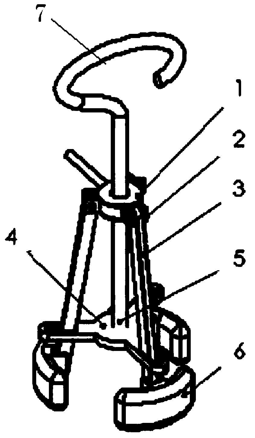
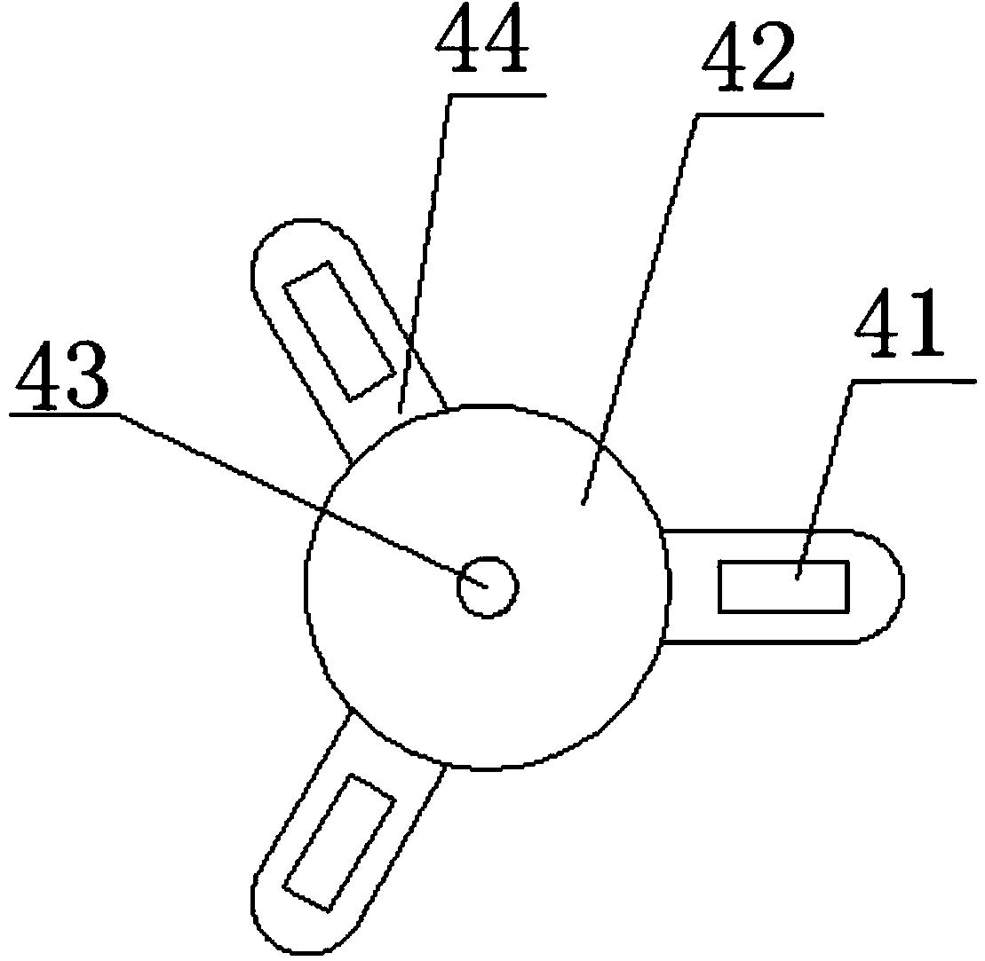
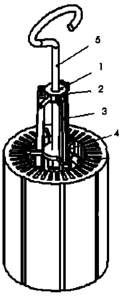
[0030] Use the lifting device with three claw rods 3. When using it, hold the fixed ring 1, push the handle 5 down to fold the claw rods 3, and put the lifting device into the middle of the motor stator with silicon steel sheets stacked together. In the hole, the outer side of the claw pad 6 is wrapped with a nylon layer. When the handle 5 is lifted up, it pulls the support plate 4 up, and the support plate 4 pushes the three claw bars 3 to the outside through the square groove 41 to form a fan. Unfold, make the claw pad 6 close to the inner diameter of the workpiece, and use friction to make the lifting device and the workpiece more and more tight. When the friction force is greater than the mass of the workpiece, the workpiece is lifted and moved to the required place. After use, move the handle 5 to the Lower the top, make the claw bar 3 draw in, just can take out the lifting device from the workpiece.

Embodiment 2

[0032] Use the lifting device with 5 claw rods 3, hold the fixed ring 1 when in use, push the handle 5 down to make the claw rods 3 close up, put the lifting device into the middle hole of the coil of the large motor, and its claws The outer side of the pad 6 is covered with a silicone layer. When the handle 5 is lifted up, it pulls the support plate 4 up, and the support plate 4 pushes the five claw rods 3 to fan out to the outside through the square groove 41, so that the claw pad 6 Close to the inner diameter of the workpiece, use friction to make the lifting device and the workpiece more and more tight, when the friction force is greater than the mass of the workpiece, use the hook of the crane to hook the hook-shaped handshake part 7 to lift the workpiece and move it to the required place. After the use is completed, the handle 5 is pushed downwards, so that the claw bar 3 is drawn in, and the lifting device can be taken out from the workpiece.


PUM


Abstract

The invention relates to a special hoisting device for a hollow cylindrical piece. The special hoisting device comprises a fixing ring (1), a plurality of claw bars (3) and a handle (5), wherein the handle (5) vertically passes through the middle of the fixing ring (1) to be connected with the middle of a supporting plate (4), the claw bars (3) are uniformly distributed around the fixing ring (1), the upper ends of the claw bars (3) are hinged with the fixing ring (1), the claw bars (3) pass through a square slot (41) in the supporting plate (4) and can slide in the square slot (41), the lower ends of the claw bars (3) are hinged with a claw pad (6) which is arc-shaped, and the top end of the arc surface is outwards. The special hoisting device is simple in structure and convenient to operate, can realize quick damage-free hoisting of a hollow cylinder, and improves the production and machining efficiency.

Description

technical field [0001] The invention relates to the field of mechanical processing auxiliary equipment, in particular to a special lifting device for hollow cylindrical parts. Background technique [0002] Hollow cylinder is the shape of parts experience in the field of machining. It is a typical motor stator with silicon steel sheets stacked together. Due to the high precision of the outer surface of many hollow cylinder parts, during the lifting process There should be no bumps. During the hoisting process of these hollow cylindrical parts, whether using bare hands or using traditional tools with clamping functions, damage to the outer surface of the cylinder cannot be avoided. If the hollow cylindrical parts are lifted during the lifting process Adding a protective layer to the outer surface of the hollow cylinder will undoubtedly increase the workload and cost, and reduce the production efficiency. This problem plagues the processing and production enterprises that need ...

Claims


Application Information

Patent Timeline
Patent Type & Authority Applications(China)
IPC IPC(8): B66C1/54
Inventor 颜从均颜小棚罗英颜从江
Owner 颜从均
Why Eureka
Try Eureka