
Polycrystalline silicon directional solidifying method and device capable of improving impurity removal effect

A technology of directional solidification and polysilicon, which is applied in chemical instruments and methods, silicon compounds, inorganic chemistry, etc., can solve the problems of low recycling rate of waste, waste of energy and raw materials, and increase of manufacturing cost, so as to achieve good cost control and reduce waste , the effect of reducing the resection rate

Inactive Publication Date: 2013-12-25
QINGDAO XINSHIJI SOLAR ENERGY TECH CO LTD
View PDF4 Cites 5 Cited by
  • Summary
  • Abstract
  • Description
  • Claims
  • Application Information

AI Technical Summary

Problems solved by technology

[0005] In the current directional solidification process of polysilicon, when the directional solidification reaches 75-85%, the solid-liquid interface in the quartz crucible tends to be horizontal and continues until the end of directional solidification, so the tail waste is cut along the horizontal direction during the final cut. Contains high metal impurities in the waste, and the metal impurities are distributed in various parts of the waste, resulting in low waste recycling rate
Generally, the removal rate of tail waste is 20-25%, that is, the yield is only 75-80%, which causes a great waste of energy and raw materials, and thus increases the manufacturing cost.

Method used


Image

  • Polycrystalline silicon directional solidifying method and device capable of improving impurity removal effect

Examples


Embodiment 1

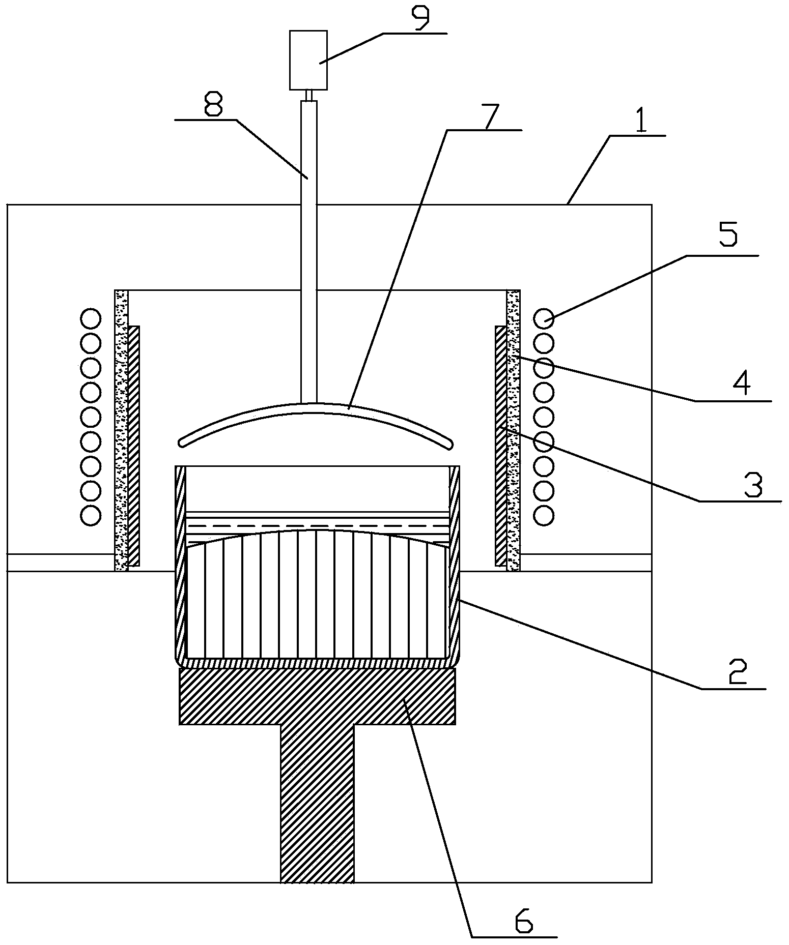
[0019] Such as figure 1 As shown, a polysilicon directional solidification device for improving the impurity removal effect includes a furnace body 1, a quartz crucible 2 is placed in the furnace body 1, and the outer wall of the quartz crucible 2 is surrounded by a graphite heating element 3 and a thermal insulation sleeve 4 sequentially from the inside to the outside. and the induction coil 5, the bottom of the quartz crucible 2 is provided with an ingot pulling mechanism 6 communicating with the bottom of the furnace body 1, a graphite tube 8 is vertically connected between the furnace body 1 and the heat preservation sleeve 4, and a graphite tube 8 is connected below the graphite tube 8 A curved graphite heater 7 is located between the insulation sleeve 4 and the quartz crucible 2 , and a drive mechanism 9 is connected to the graphite tube 8 located outside and above the furnace body 1 .

[0020] Wherein, the curved graphite heater 7 is convex. When the curved graphite he...

Embodiment 2

[0024] Adopt the device described in embodiment 1, carry out directional solidification:

[0025] (1) Put 500kg of industrial silicon in the quartz crucible 2, turn on the mechanical pump to evacuate the furnace body 1 to 800Pa, then turn on the Roots pump and continue to evacuate to 0.1Pa;

[0026] (2) Turn on the induction coil 5 to act on the graphite heating element 3 to raise the temperature of the silicon material in the quartz crucible 2 to 1500°C. After 10 hours, the silicon material is heated and melted to form a silicon melt;

[0027] (3) After 8 hours of heat preservation, turn off the Roots pump and the mechanical pump in turn. Fill the furnace body 1 with argon gas, and start the ingot pulling mechanism 6;

[0028] (4) Before the quartz crucible 2 is pulled down, place the thermocouple on the outer bottom of the quartz crucible 2 and place it in the air to monitor the temperature of the silicon melt and solid interface in real time. When the displayed temperature...


PUM


Abstract

The invention belongs to the field of polycrystalline silicon purification, and particularly relates to a polycrystalline silicon directional solidifying method and device capable of improving the impurity removal effect. A curved graphite heater is additionally arranged in an existing device, when silicon liquid is directionally solidified by 75% to 85%, the silicon liquid on the upper portion is influenced by the curved graphite heater above a quartz crucible in a heat radiating mode, and therefore the curved degree of a solid liquid interface inside the quartz crucible is enlarged. The polycrystalline silicon directional solidifying method and device have the advantages that distribution of metal impurities has the directionality in a directionally solidified silicon ingot and can be conveniently cut off, and the cutting rate of waste on the tail portion is reduced; the device is easily transformed, on the basis of the existing device, only the curved graphite heater is additionally arranged above the quartz crucible, and the cost is well controlled; waste of raw materials is reduced, and the cost of polycrystalline silicon raw materials is greatly reduced.

Description

technical field [0001] The invention belongs to the field of polysilicon purification, and in particular relates to a polysilicon directional solidification method and a device for improving the impurity removal effect. Background technique [0002] At present, my country has become the world's largest energy production and consumption country, but the per capita energy consumption level is still very low. With the continuous development of the economy and society, my country's energy demand will continue to grow. In response to the current energy shortage, countries around the world are thinking deeply, and are working hard to improve energy efficiency, promote the development and application of renewable energy, and reduce the impact on energy consumption. Reliance on imported oil to enhance energy security. [0003] As one of the important development directions of renewable energy, solar photovoltaic power generation has developed rapidly in recent years, and its proport...

Claims


Application Information

Patent Timeline
Patent Type & Authority Applications(China)
IPC IPC(8): C01B33/037
Inventor 姜大川刘子成谭毅
Owner QINGDAO XINSHIJI SOLAR ENERGY TECH CO LTD
Learn More