High temperature high pressure ceramic valve

A high-temperature, high-pressure, ceramic valve technology, applied in the field of ceramic valves, can solve the problems of not being able to adapt to high wear, strong corrosion, affecting system operation stability, and short service life, so as to achieve extended life, good sealing effect, and improved mechanical properties. Effect

Active Publication Date: 2013-12-25
YANTAI KINGWAY SCI & TECH
View PDF5 Cites 7 Cited by
  • Summary
  • Abstract
  • Description
  • Claims
  • Application Information

AI Technical Summary

Problems solved by technology

[0002] At present, the valves commonly used in various industries are metal valves. The use of metal valves has a history of hundreds of years. Although their structures and materials have been continuously improved, they cannot adapt to harsh working conditions such as high wear and strong corrosion due to the limitations of metal material properties. The main problem is that the service life is short and the leakage is serious, which greatly affects the stability of the system operation.

Method used


Image

  • High temperature high pressure ceramic valve
  • High temperature high pressure ceramic valve

Examples


Embodiment Construction

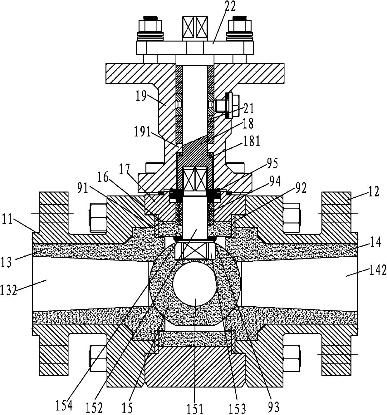
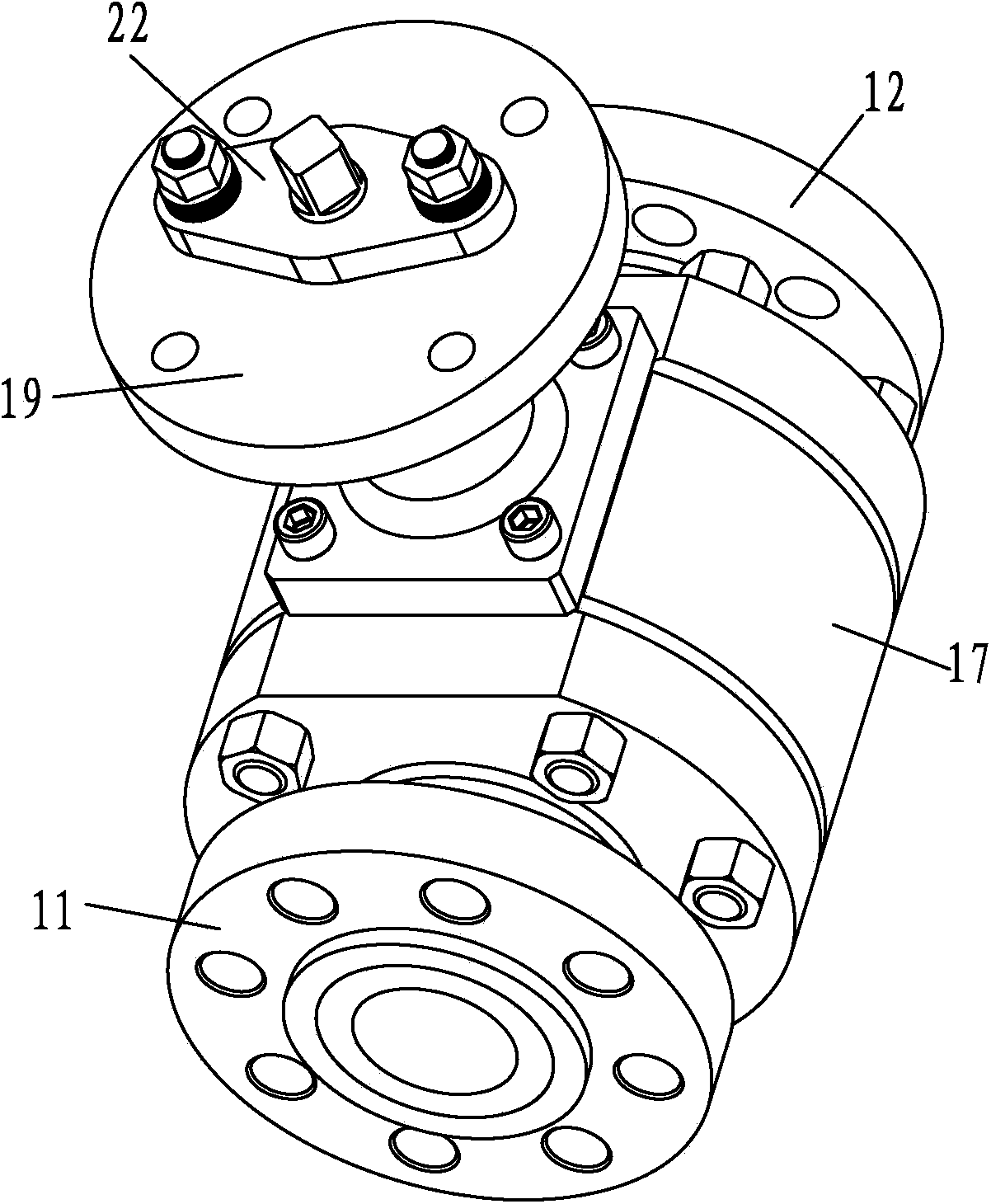
[0026] Such as figure 1 , 2 As shown, a high-temperature and high-pressure ceramic valve includes left and right flanges 11, 12, left and right valve seats 13, 14, a ball 15, a valve inner lining 16, a valve body 17, left and right flanges 11, 12 Set respectively outside the left and right valve seats 13 and 14, between the left valve seat 13 and the left flange 11, between the right valve seat 14 and the right flange 12 are all interference fits, and the centers of the left and right valve seats are all set Runner 132,142 is arranged, and spheroid 15 is arranged between left and right valve seat 13,14, and the axis of left and right valve seat 13,14 all passes through the center of spheroid 15, and spheroid 15 center is provided with through hole 151, and spheroid 15 is provided with a stem hole 153, the stem hole is a blind hole, the stem 152 is installed in the stem hole 153, the valve body 17 is clamped between the left and right flanges 11, 12, the valve body lining 16 ...


PUM


Abstract

A high temperature high pressure ceramic valve comprises a left flange, a right flange, a left valve seat, a right valve seat, a sphere, a valve body lining and a valve body; the left flange and the right flange are sleeved outside the left valve seat and the right valve seat; centers of the left valve seat and the right valve seat are provided with flow channels; the sphere is arranged between the left valve seat and the right valve seat; a through hole is formed in the center of the sphere; a valve rod is connected to the upper end of the sphere; the valve body is clamped between the left flange and the right flange; the valve body lining is clamped between the left valve seat and the right valve seat; the valve body is sleeved outside the valve body lining; the left flange, the right flange and the valve body are mutually fixed; through holes are formed in the valve body lining and the valve body; the valve rod extends out from the through hole which is formed in the valve body; the left valve seat, the right valve seat, the sphere and the valve body lining are made of ceramic materials. The high temperature high pressure ceramic valve has the advantages of being high temperature resistant and corrosion resistant, enabling the high temperature resistant performance to be greatly improved and enabling the service life under poor working conditions to be prolonged.

Description

technical field [0001] The invention relates to a valve body, in particular to a ceramic valve. Background technique [0002] At present, the valves commonly used in various industries are metal valves. The use of metal valves has a history of hundreds of years. Although their structures and materials have been continuously improved, they cannot adapt to harsh working conditions such as high wear and strong corrosion due to the limitations of metal material properties. The main problem is that the service life is short and the leakage is serious, which greatly affects the stability of the system operation. Traditional metal valves are in urgent need of complete innovation in terms of materials, design and manufacturing processes. The application of ceramic materials in ball valves can make good use of the natural characteristics of ceramic corrosion resistance and wear resistance, greatly improving the high temperature resistance and wear resistance of ball valves, making t...

Claims


Application Information

Patent Timeline
Patent Type & Authority Applications(China)
IPC IPC(8): F16K5/06F16K5/08F16K27/06
Inventor 金浩军姜雅周王吉慧
Owner YANTAI KINGWAY SCI & TECH
Why Eureka
Try Eureka