
Light source containing internal light distribution curve

A light distribution and curve technology, which is applied in the field of light sources with internal light distribution curves, can solve the problems of glare, large light pollution, small cut-off angle, zebra effect, etc., and achieve the effects of improving the life of the light source, improving the reflectivity, and being easy to use

Inactive Publication Date: 2013-12-25
杨罗定
View PDF15 Cites 1 Cited by
  • Summary
  • Abstract
  • Description
  • Claims
  • Application Information

AI Technical Summary

Problems solved by technology

[0003] Because the external reflector lamps are susceptible to pollution, oxidation, dust accumulation and rain erosion, after a period of use, the effective utilization rate of light will be greatly reduced. During the validity period of the light source, the reflection efficiency is only 85% to 50%. The lamp efficiency is 76-45%, the system light efficiency is 100-35 lumen watts, and the whole lamp is large in size, heavy in weight, high in energy consumption, and consumes a lot of metal materials
[0004] Most of the LED light sources adopt a flat-plate structure, and the uniformity and brightness of the light on the road are poor. Its heat dissipation is slow, the light decay is large, the cut-off angle is small, and it will cause the zebra effect, and the glare is serious. The driver's line of sight is particularly dazzling, and heat dissipation lamps need to be added, so it is expensive

Method used


Image

  • Light source containing internal light distribution curve
  • Light source containing internal light distribution curve
  • Light source containing internal light distribution curve

Examples


Embodiment Construction

[0017] Embodiments of the present invention will be further described in detail below in conjunction with the accompanying drawings.

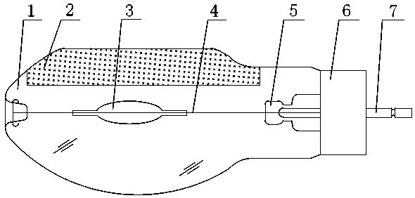
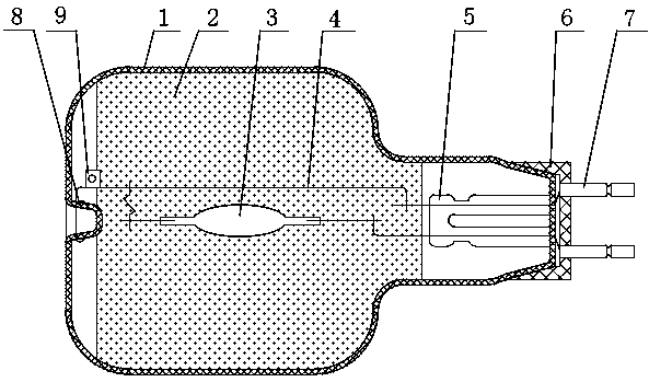
[0018] The illuminant adopts the ion luminescent ball 3 .

[0019] The lamp cap is a screw lamp cap 10 or a ceramic seat 6 fixed with two metal rods 7 .

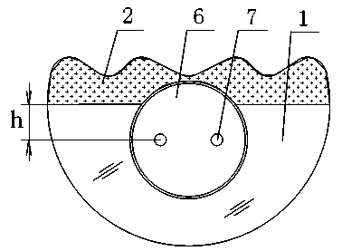
[0020] There is a recessed pillar 8 on one end of the inside of the glass bulb 1, and the lamp cap at the other end is a conventional screw lamp cap 10, or a ceramic seat 6 with two metal rods 7, and the lower surface is a conventional smooth arc surface, that is, the light source transmission area. The shape of the traditional upper surface has been greatly improved. The upper surface is a regular wavy arc surface, which is symmetrical to the center of the transmission area, and the light-transmitting surface and the reflecting surface are enlarged.

[0021] On the inner surface of the wavy arc of the glass bulb 1, a layer of reflective film is sprayed, that is, the reflective coating 2 mat...


PUM


Abstract

The invention relates to a light source containing an internal light distribution curve. The light source comprises a glass bulb with a reflective coating, a lamp cap, a stem and a luminophor, wherein the area of the reflective coating is less than the area of a transmission area, and the distance between the edge of the reflective coating and the center of the transmission area H is equal to 1 / 2 to 1 / 3R (the maximum radius of the glass bulb); the upper surface of the glass bulb is a regular wave arc surface, and the reflective coating and the upper surface of the glass bulb are matched in shape; and the luminophor is an ion luminous ball. The shape of the traditional glass bulb is changed, the internal light distribution curve is a double-wing flat curve, the angle is greater than 120 degrees, a huge lamp does not need to be matched, the reflection rate of the light source is increased to 98%, the luminous efficiency is greater than 92%, the luminous efficiency of the system is greater than 110 to 160 lumens watts, the illumination and light distribution is more uniform, the interference of glare is reduced, the light source meets the requirement of GB50034-2004 and the Ministry of Construction CJJ45-2006 ' city road lighting design standard' that the waterproof and dustproof grade achieves IP65 above, the life of the light source is prolonged, the intensity of the light source and the irradiation effect are improved, and the purposes of energy saving and environmental protection, low price and convenience in use are achieved.

Description

technical field [0001] The invention relates to an illumination light source, in particular to a light source with an internal light distribution curve, which has a reflective function and has a long service life, and is suitable for installation and use in arterial traffic roads, sidewalks, engineering construction, tunnels, agricultural factories and other places. Background technique [0002] Now high-intensity gas discharge lamps and LED light sources are widely used in roads, squares, agricultural factories and other occasions that require a lot of lighting and high brightness. In order to achieve uniformity of illumination and improve light utilization, they all need to be equipped with reflective light It can be used in lamps such as controllers, electrical boxes, triggers, driving power supplies, and housings with heat dissipation. [0003] Because the external reflector lamps are susceptible to pollution, oxidation, dust accumulation and rain erosion, after a period...

Claims


Application Information

Patent Timeline
IPC IPC(8): F21S2/00F21V3/04F21V3/02F21V13/04
Inventor 杨罗定
Owner 杨罗定
Learn More