Method for automatically correcting temperature drift of electrical vortex sensor

An eddy current sensor, temperature drift technology, applied to instruments and other directions, can solve the problems of high price, increased number of leads, lack of versatility, etc., to achieve the effect of good versatility and simple structure

Active Publication Date: 2013-12-25
UNIV OF SCI & TECH OF CHINA
View PDF6 Cites 38 Cited by
  • Summary
  • Abstract
  • Description
  • Claims
  • Application Information

AI Technical Summary

Problems solved by technology

[0004] The current main compensation (correction) measures mainly include: 1. Increase the differential compensation coil. This method increases the volume and complexity of the probe, and is not universal. It cannot perform temperature compensation for different detection targets, except for the compensation coil. In addition, it is also necessary to install a suitable induction conductor surface for the differential coil
2. Add a non-inductive coil with the same resistance value to sense temperature changes to provide compensation. This method can only eliminate the temperature drift caused by the temperature change of the detection coil resistance itself, the temperature drift of the inductor, and the resistivity of the target conductor Drift caused by temperature drift cannot be compensated for
3. Use the temperature measuring element to measure the temperature and realize the correction of temperature drift. Although this method is fe

Method used


Image

  • Method for automatically correcting temperature drift of electrical vortex sensor
  • Method for automatically correcting temperature drift of electrical vortex sensor
  • Method for automatically correcting temperature drift of electrical vortex sensor

Examples


Embodiment Construction

[0040] The implementation of the present invention will be described in detail below by taking the eddy current displacement sensor adopting the correction method of the present invention as an example.

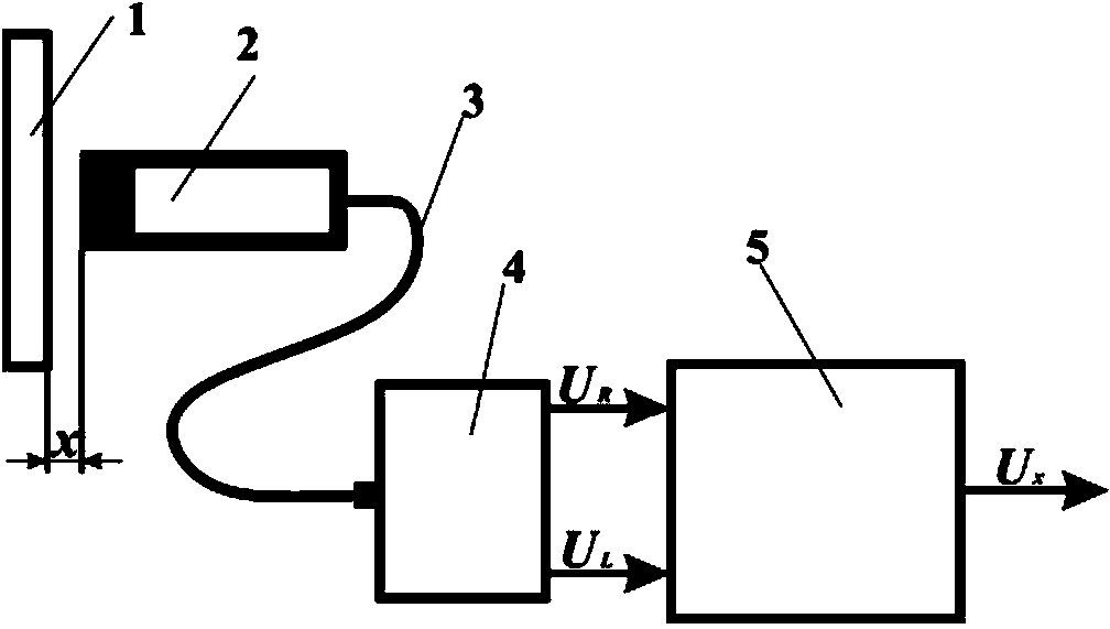
[0041] like figure 1 As shown, the eddy current displacement sensor system based on the present invention is mainly composed of a detection target 1 , an eddy current sensor probe 2 , a coaxial cable 3 , an impedance measurement module 4 and a correction operation module 5 . The signal demodulation circuit part of the temperature drift self-correcting eddy current sensor in this embodiment is mainly composed of a signal source 12 , an impedance measurement module 4 and a correction operation module 5 .

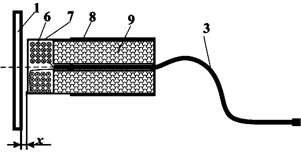
[0042] First make the eddy current sensor probe 2, such as figure 2 shown. Copper enameled wire with a certain diameter is wound on a quartz glass tube to form a detection coil 6. The detection coil can be wound into a single-layer helical shape, or it can be wound into a ...


PUM


Abstract

The invention provides a method for automatically correcting temperature drift of an electrical vortex sensor. According to the method, a certain impedance measuring circuit is utilized to obtain the equivalent inductance and the resistance of a detection coil, the relationship, changing along with temperature and measurement, of the inductance and the resistance of the detection coil is utilized to remove the influence of temperature changes and extract actual measured change information. According to the method, signals of the vortex sensor composed of an impedance measuring module (4) and a rectification calculating module (5) is used for conditioning the circuit, so that to-be-measured information is obtained, rectification is conducted automatically, and the influence of temperature changes is removed at the same time. According to the method, when temperature drift is rectified, no extra probes or coils or temperature sensors are further arranged, and temperature drift rectification effect is remarkable. Moreover, the method has the advantages of being wide in application range, simple in structure, easy to implement and the like. When the method is used for automatically rectifying the temperature drift of a probe of the electrical vortex sensor, temperature drift coefficients can generally be reduced to below 5nm/DEG C from 500nm/DEG C.

Description

technical field [0001] The invention relates to the field of eddy current sensors, in particular to an automatic correction method for temperature drift of the eddy current sensor. Background technique [0002] The eddy current displacement sensor uses an induction coil with high-frequency excitation to generate an induced eddy current in the target conductor, and converts the distance change between the detection coil and the measured target into a change in the impedance (including inductance and resistance) of the induction coil, and the signal conditioning circuit Displacement information is obtained by measuring changes in search coil parameters. Eddy current sensors are very widely used in displacement, vibration, angle and velocity, or thickness, resistivity and temperature measurement in various industrial field and experimental researches. Due to the characteristics of the eddy current sensor itself, it has many advantages such as high stability, insensitivity to e...

Claims


Application Information

Patent Timeline
IPC IPC(8): G01D18/00
Inventor 冯志华王洪波刘永斌李伟陈建
Owner UNIV OF SCI & TECH OF CHINA
Why Eureka
Try Eureka