Flow distortion simulation device

A simulation device and flow field technology, which is applied in the aviation field, can solve the problems of low space utilization, high construction cost, high maintenance cost, and high test cost, and achieve the improvement of simulation accuracy and automation, excellent structure and sealing, The effect of improving test efficiency

Active Publication Date: 2013-12-25
BEIJING POWER MACHINERY INST
View PDF7 Cites 16 Cited by
  • Summary
  • Abstract
  • Description
  • Claims
  • Application Information

AI Technical Summary

Problems solved by technology

[0003] The fixed distortion simulator has the following disadvantages: in order to achieve the specified distortion index and carry out the engine wheezing test, it is often necessary to carry out multiple rounds of trials on the plugboards with different clogging ratios, which consumes a lot of manpower and material resources, and the test efficiency is low; the installation and operation are complicated, and every Every time you change the distortion simulation state, you need to disassemble the distortion simulation board and re-seal it. Since only one distortion state test can be done in one test, it takes a long time to complete all the calibration tests of a set of distortion simulators, and the test cost is high.
[0004] Movable distortion simulators are divided into hydraulic distortion simulators and electric distortion simulators. Among them, hydraulic distortion simulators are bulky, with high construction and maintenance costs, and each test requires a comprehensive system inspection, which takes a long time to prepare for the test. Transmission displacement accuracy is low
However, the electric push rod transmission box of the electric distortion simulation device is large in size, low in space utilization, limited in use, and cannot guarantee the verticality of the simulation plate inside the flow channel

Method used


Image

  • Flow distortion simulation device
  • Flow distortion simulation device
  • Flow distortion simulation device

Examples


Embodiment Construction

[0026] Embodiments of the present invention are described in detail below, examples of which are shown in the drawings, wherein the same or similar reference numerals designate the same or similar elements or elements having the same or similar functions throughout. The embodiments described below by referring to the figures are exemplary only for explaining the present invention and should not be construed as limiting the present invention.

[0027] In describing the present invention, it should be understood that the terms "center", "longitudinal", "transverse", "upper", "lower", "front", "rear", "left", "right", " The orientations or positional relationships indicated by "vertical", "horizontal", "top", "bottom", "inner" and "outer" are based on the orientations or positional relationships shown in the drawings, and are only for the convenience of describing the present invention and Simplified descriptions, rather than indicating or implying that the device or element refe...


PUM


Abstract

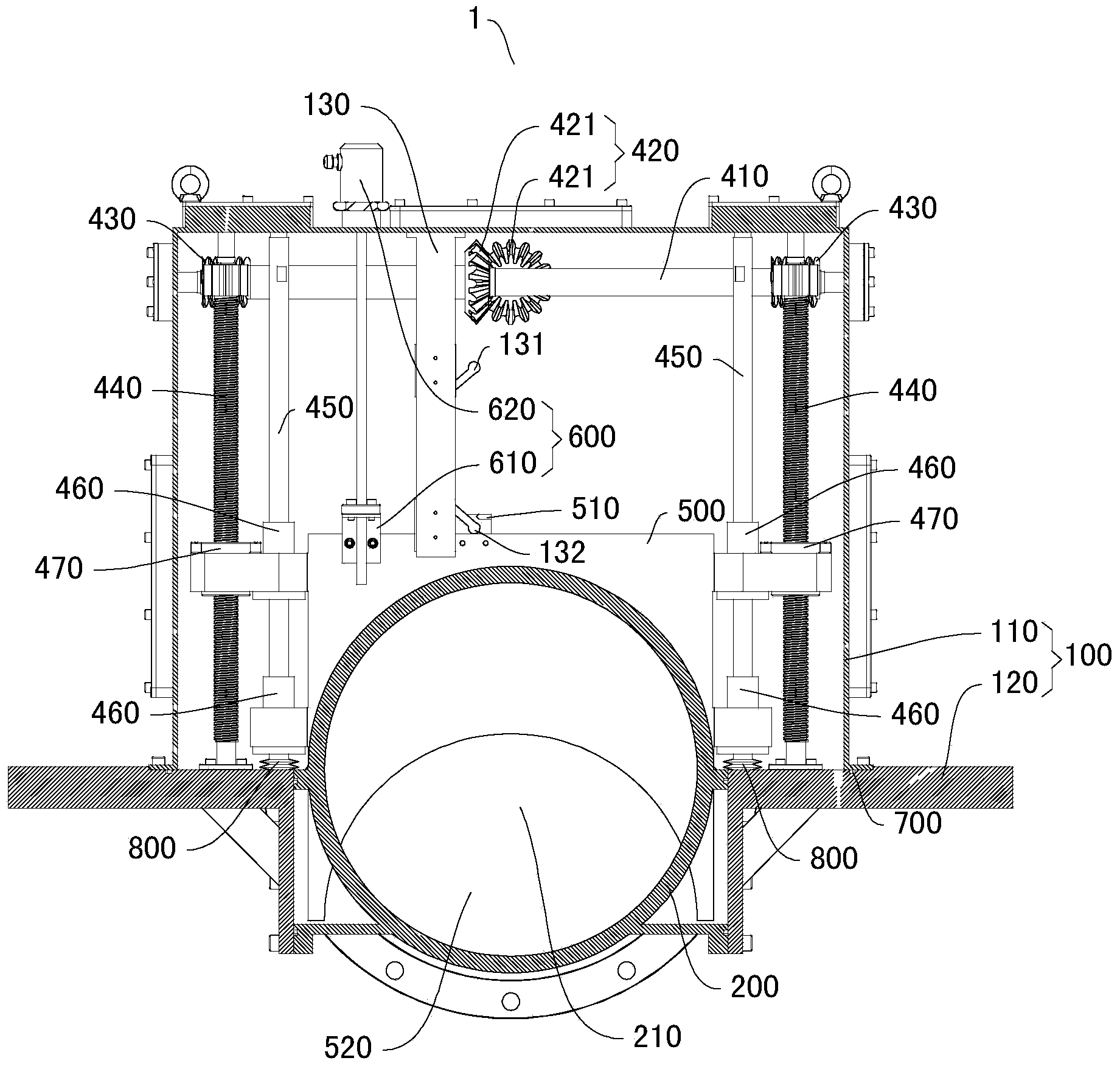
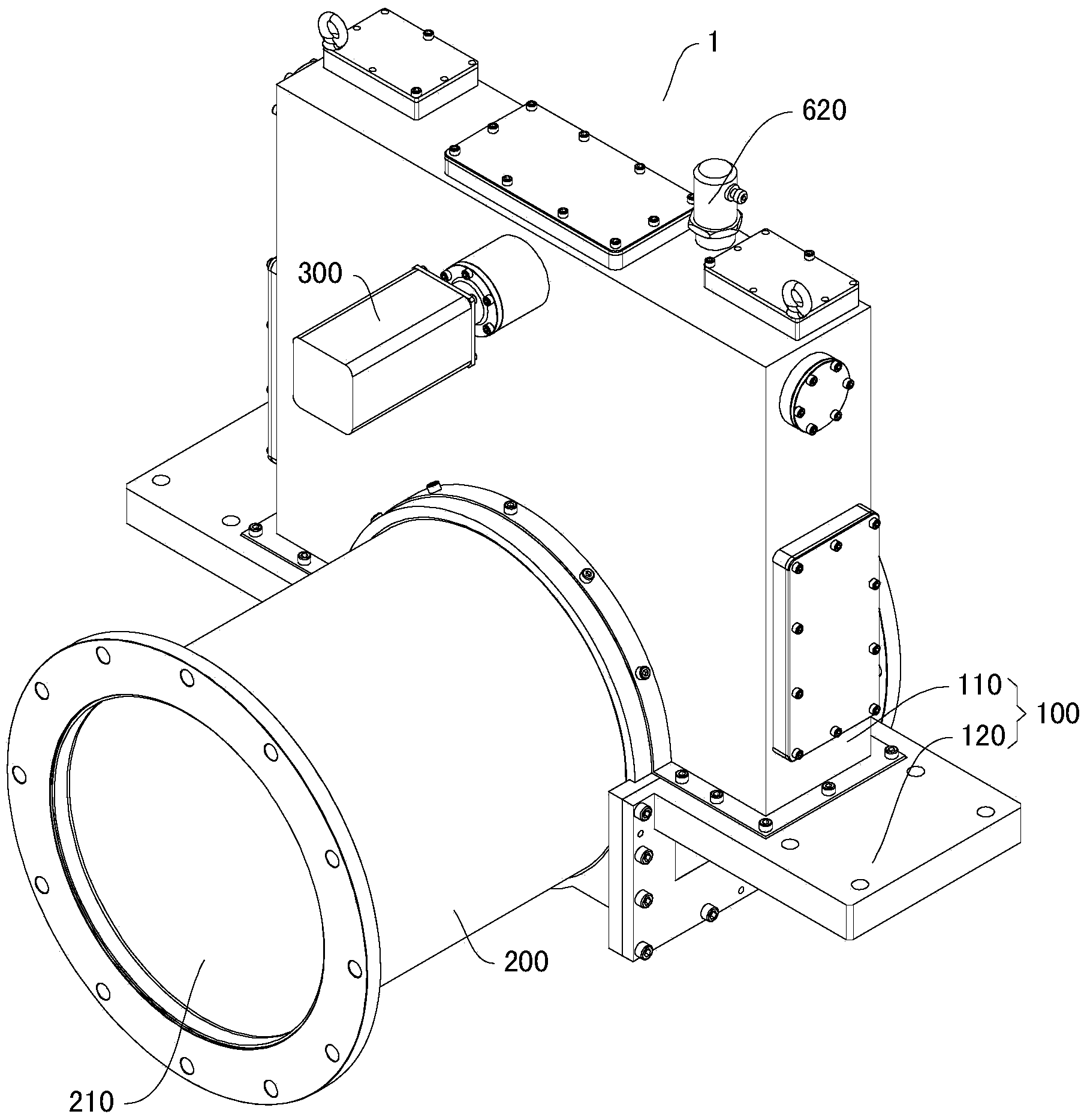
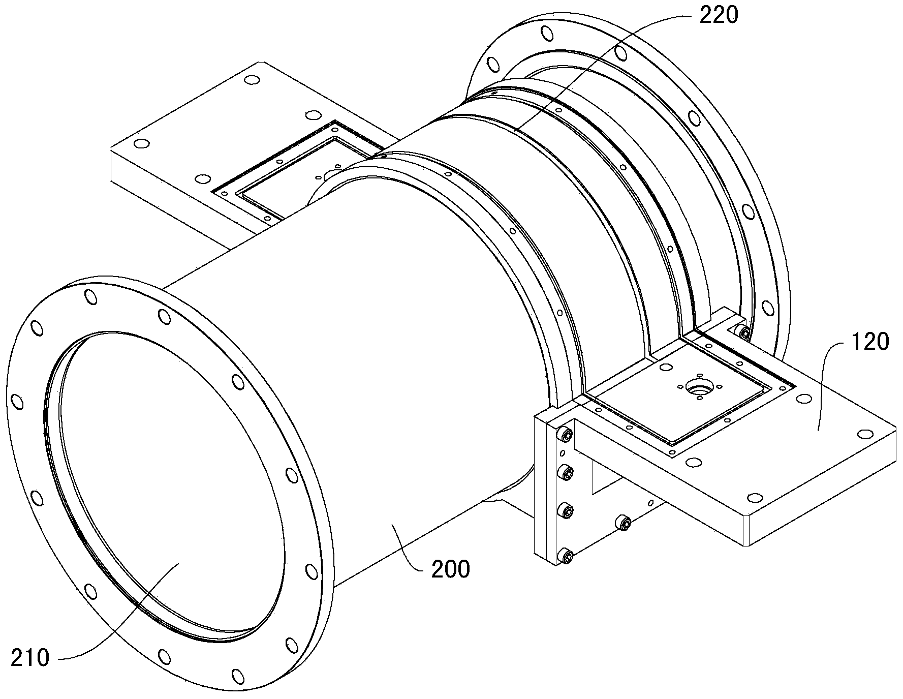
The invention discloses a flow distortion simulation device which comprises a tank body, a tube body, a motor, a worm, a bevel gear assembly, a worm gear, a lead screw, a guiding rod, a linear bearing, a gear nut, an inserting plate, a displacement detection assembly and a controller. The tube body is arranged on the tank body, the worm is arranged in the tank body, the bevel gear assembly is respectively connected with the motor and the worm, the worm gear is arranged on the worm, the lead screw is meshed with the worm gear, the linear bearing is arranged on the guiding rod, the gear nut is arranged on the guiding rod and is in screw-thread fit with the lead screw, the inserting plate is respectively connected with the linear bearing and the gear nut, and the controller is respectively connected with the displacement detection assembly and the motor. The flow distortion simulation device has the advantages of being capable of meeting requirements of a turbofan engine inlet distortion resistant test and an engine surge test, small in occupied space, continuous and adjustable in distortion index, convenient to install and operate, high in simulation accuracy and degree of automation, capable of improving the test efficiency, reducing the test cost, reducing the workloads of people and the like.

Description

technical field [0001] The invention relates to the field of aviation, in particular to a flow field distortion simulation device. Background technique [0002] Stability is one of the important indicators of an aero-worm gear engine, and the external destabilizing factor that has the greatest impact on engine stability is pressure distortion. At present, the plugboard simulation method is used to provide the pressure distortion flow field for the engine matching test. Specifically, a plugboard simulation device is installed upstream of the engine. The total pressure distortion and turbulent degree of the total pressure are simulated in front of the engine to simulate the characteristics of the flow field at the outlet of the intake port in a certain state, so as to carry out the compatibility test between the intake port and the engine. There are two types of existing pressure flow field distortion simulators: fixed distortion simulators and movable distortion simulators. ...

Claims


Application Information

Patent Timeline
Patent Type & Authority Applications(China)
IPC IPC(8): G01M15/02
Inventor 赵英张韬王汉权张金良陈宝延
Owner BEIJING POWER MACHINERY INST
Why Eureka
Try Eureka