Transient electromagnetic low-mutual-inductance foldable type coil

A transient electromagnetic and foldable technology, applied in the direction of electrical/magnetic detection for logging records, etc., can solve the problems of not realizing foldable structural components, not realizing low mutual inductance design, and inconvenient installation and disassembly. , to achieve the effect of light weight, easy assembly and disassembly, and reduced mutual inductance

Active Publication Date: 2013-12-25
ANHUI HUIZHOU GEOLOGY SECURITY INST
View PDF11 Cites 2 Cited by
  • Summary
  • Abstract
  • Description
  • Claims
  • Application Information

AI Technical Summary

Problems solved by technology

[0003] At present, there are various designs of transient coils and supports, such as application numbers "201220429932.4, 200710115317.X, 201120108342.7, 201120234412.3, 201210270050.2", but none of them have realized foldable structural components, nor have they realized low mutual inductance design (transmitting coil and There is a gap between the receiving coils), affected by the complex conditions in the mine, it is easy to cause disadvantages such as poor anti-interference ability, unstable receiving signal, difficult movement, inconvenient installation and disassembly, etc.

Method used


Image

  • Transient electromagnetic low-mutual-inductance foldable type coil
  • Transient electromagnetic low-mutual-inductance foldable type coil
  • Transient electromagnetic low-mutual-inductance foldable type coil

Examples


Embodiment 1

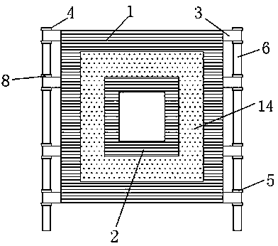
[0021] Such as figure 1 As shown, the present invention includes a transmitting coil 1 and a receiving coil 2, both of which are respectively fixedly arranged on a foldable waterproof fiber fabric base 14 (rubber cloth or plastic cloth can also be used). There is a gap between the two coils, the distance is 0.2 meters, which can reduce the mutual inductance, because:

[0022] The self-inductance coefficient of the known loop is:

[0023]

[0024] According to the Biot-Safar law, it can be rewritten as:

[0025]

[0026] Mutual inductance coefficient .

[0027] That is, the mutual inductance is directly proportional to the self-inductance.

[0028] and

[0029] Among them, K is a constant, b=

[0030] found by derivation , that is, the larger the distance between the two coils, the smaller the mutual inductance. Therefore, in the case of a certain transmitting coil, the smaller the receiving coil, the smaller the influence of mutual inductance. This distan...

Embodiment 2

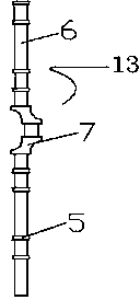
[0033] Such as figure 2 As shown, the difference from Embodiment 1 is that the two rod sleeves in the middle of the combined longitudinal strut 13 are in a zigzag shape, that is, the zigzag rod sleeve 7, which can form a handle after being connected with a rod. Handle for folding transmitter and receiver coils.

[0034] The material of the rod cover and the pole in the first or second embodiment can be a non-conductor, such as a glass fiber tube or a plastic rod. Either strut 6 can be pulled off or unscrewed during carrying.

[0035] image 3 It is a schematic diagram of the structure of two zigzag rod sleeves 7 in the middle of the longitudinal strut 13 in the second embodiment. Longitudinal strut 13 also can be made as figure 1 shown in, or one-piece.

[0036] Such as Figure 4 As shown, the foldable transmitting and receiving coil can be folded one or more times along the left and right folding center line 9 of the coil, the left and right arbitrary folding line 10,...


PUM


Abstract

The invention relates to a transient electromagnetic low-mutual-inductance foldable type coil which comprises a transmitting coil and a receiving coil. The transmitting coil and the receiving coil are respectively and fixedly arranged on a foldable bottom liner, the transmitting coil is placed on the periphery of the receiving coil, and a gap is reserved between the transmitting coil and the receiving coil. A plurality of straps are arranged on the two sides of the bottom liner, and the bottom liner is connected with combined type longitudinal supporting rods placed on the two sides of the transmitting coil through the straps. According to the transient electromagnetic low-mutual-inductance foldable type coil, on one hand, the transmitting coil and the receiving coil are fixed in the same plane through components such as rod sleeves, the gap is reserved between the transmitting coil and the receiving coil, mutual inductance caused by current changes in the two coils can be effectively reduced, and the signal to noise ratio is improved; on the other hand, by the aid of the foldability of the transmitting coil and the receiving coil, the occupied size of the coils in the manual carrying process can be decreased, the coils can be connected with an instrument conveniently, and great convenience is brought to usage of people.

Description

technical field [0001] The invention relates to a transient electromagnetic transmitting and receiving coil, in particular to a roadway transient electromagnetic low mutual inductance foldable transmitting and receiving coil. Background technique [0002] As we all know, the transient electromagnetic method is based on the principle of electromagnetic induction, using an ungrounded coil to send a primary electromagnetic field underground, and using an ungrounded coil to observe the secondary eddy current field during the intermittent period of the primary electromagnetic field to analyze the physical property differences of different lithologic formations. Due to the advantages of small volume effect, high work efficiency, high vertical and horizontal resolution, and sensitive response to low-resistance bodies, mine-used transient electromagnetic method is widely used in mine water inrush prediction and advanced prediction. The structure and performance of transmitting and r...

Claims


Application Information

Patent Timeline
Patent Type & Authority Applications(China)
IPC IPC(8): G01V3/28
Inventor 唐润秋周官群陈光明戚俊李纯阳黄兰英李张鹏李准
Owner ANHUI HUIZHOU GEOLOGY SECURITY INST
Why Eureka
Try Eureka