Bipolar plate for flow batteries

A flow battery and bipolar plate technology, applied in battery electrodes, circuits, electrical components, etc., can solve problems such as corrosion of bipolar plates, damage to bipolar plates, etc., to extend service life, improve service life, and ensure stable operation. Effect

Active Publication Date: 2013-12-25
DALIAN RONGKE POWER
View PDF5 Cites 10 Cited by
  • Summary
  • Abstract
  • Description
  • Claims
  • Application Information

AI Technical Summary

Problems solved by technology

[0003] Both sides of the bipolar plate are electrode frames, the electrode frame is a hollow structure, and there are positive and negative electrodes inside. The e

Method used


Image

  • Bipolar plate for flow batteries
  • Bipolar plate for flow batteries
  • Bipolar plate for flow batteries

Examples


Embodiment 1

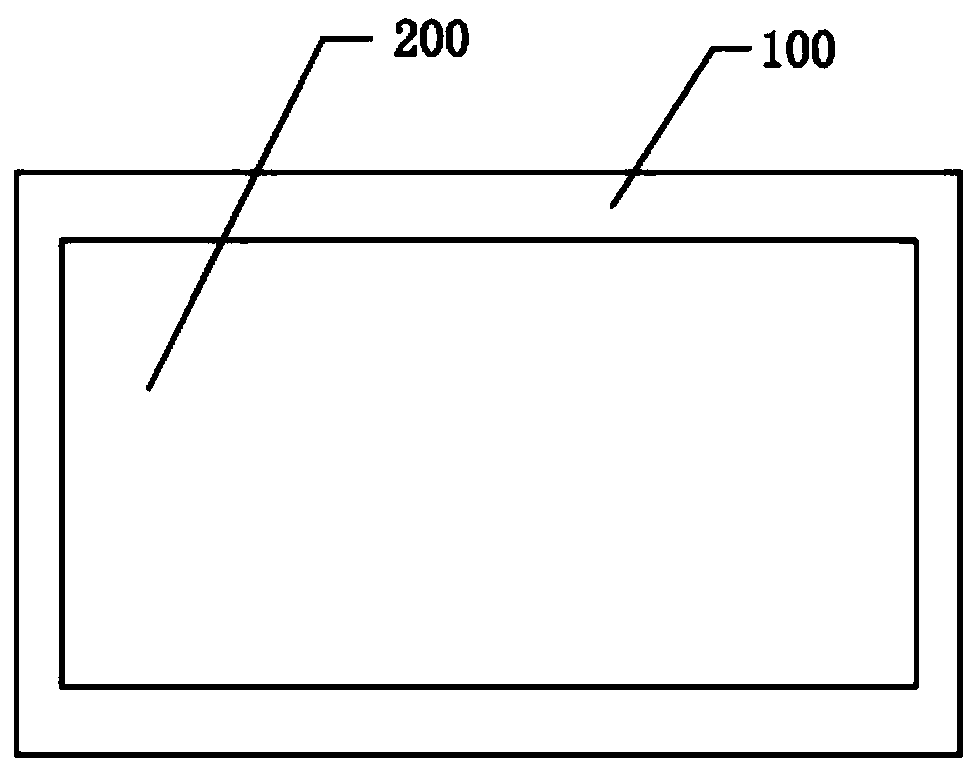
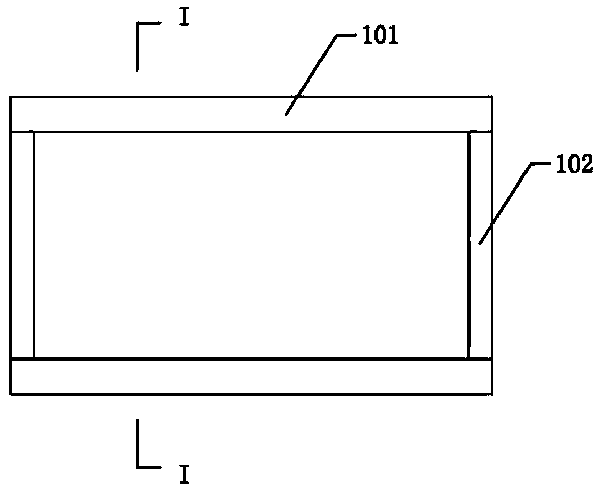
[0030] A bipolar plate for a liquid flow battery has a size of 500mm in length and 400mm in width. The bipolar plate is divided into an electrode area 200 and a non-electrode area 100, such as figure 1 As shown; the non-electrode area 100 is divided into a flow channel area 101 and a non-flow channel area 102, such as figure 2 shown.

[0031] Such as figure 2 As shown, the flow channel area 101 of the bipolar plate is located on the long side of the bipolar plate, and the non-flow channel area 102 of the bipolar plate is located on the short side of the bipolar plate. The width of the flow channel area 101 of the bipolar plate is 20mm. The non-runner area 102 of the plate is 10 mm wide. Such as image 3 As shown, the thickness of the electrode region 200 of the bipolar plate is equal to the thickness of the non-electrode region 100, which is 2mm. The material of the non-runner area 102 of the bipolar plate and the material of the electrode area 200 are carbon-plastic co...

Embodiment 2

[0033] A bipolar plate for a liquid flow battery has a size of 1000 mm in length and 700 mm in width. The bipolar plate is divided into an electrode area 200 and a non-electrode area 100 ; the non-electrode area 100 is divided into a flow channel area 101 and a non-flow channel area 102 .

[0034] The flow channel area 101 of the bipolar plate is located on the long side of the bipolar plate, and the non-flow channel area 102 of the bipolar plate is located on the short side of the bipolar plate. The width of the track region 102 is 12 mm, and the thickness of the electrode region 200 of the bipolar plate is 2 mm. The non-electrode area 100 of the bipolar plate is covered with a layer of polyethylene insulating material with a thickness of 1 mm, so the thickness of the non-electrode area 100 of the bipolar plate is 4 mm, and the flow channel area 101 and the non-flow channel area 102 of the bipolar plate have the same thickness. The polyethylene insulating material is connect...


PUM

PropertyMeasurementUnit
Thicknessaaaaaaaaaa
Widthaaaaaaaaaa
Widthaaaaaaaaaa

Abstract

The invention relates to a bipolar plate for flow batteries, belonging to the field of flow batteries. The bipolar plate is divided into an electrode zone and a non-electrode zone, wherein the electrode zone is a zone where the flow battery bipolar plate contacts the adjacent electrodes on the two sides, and the rest is the non-electrode zone; the non-electrode zone is divided into a flow channel zone and a non-flow channel zone; the flow channel zone is a zone where the non-electrode zone contacts flow-channel-bearing frames of the adjacent electrode frames on the two sides, and the rest of non-electrode zone is the non-flow channel zone; and the flow channel zone is an anti-corrosion insulation zone. The flow channel zone of the bipolar plate is the anti-corrosion insulation zone, and the bipolar plate flow channel zone in contact with the flow channel zone of the electrode frame is set as the anti-corrosion insulation zone so as to achieve the goal of preventing electrochemical corrosion, thereby prolonging the service life of the bipolar plate and ensuring the stable operation of the flow battery.

Description

technical field [0001] The invention relates to a bipolar plate for a liquid flow battery, belonging to the field of liquid flow batteries. Background technique [0002] All-vanadium redox flow battery is one of the preferred technologies for large-scale energy storage applications, and the development, design and application of high-power stacks is an inevitable trend. The stack is the core component of the all-vanadium redox flow battery, and its performance directly determines the performance and cost of the entire system. The basic structure of the stack includes current collector plate, sealing structure, electrode frame, electrode and ion exchange membrane. The bipolar plate has the function of transferring electrons and separating the positive and negative electrolytes, and the functioning area is the electrode area. The opposite non-electrode area needs to be protected, otherwise the bipolar plate will be damaged due to oxidation, corrosion and other reasons. [00...

Claims


Application Information

Patent Timeline
IPC IPC(8): H01M4/86H01M4/88
CPCY02E60/50
Inventor 马相坤张华民许晓波杨振坤王晓丽姜宏东
Owner DALIAN RONGKE POWER
Why Eureka
Try Eureka