Heat sink insulated liquid refrigeration semiconductor laser and stack array thereof

A semiconductor and laser technology, used in the field of liquid refrigeration semiconductor lasers, can solve the problems of high water quality requirements for refrigeration liquids, blockage of microchannel heat sinks, and restrictions on heat dissipation efficiency, avoiding electrochemical corrosion, reducing chip stress, and eliminating processes. Effect

Inactive Publication Date: 2016-06-22
FOCUSLIGHT TECH
View PDF3 Cites 10 Cited by
  • Summary
  • Abstract
  • Description
  • Claims
  • Application Information

AI Technical Summary

Problems solved by technology

[0004] 1) Micro-channel liquid-cooled semiconductor lasers can achieve higher power because the micro-channel heat sink dissipates heat very well (there are tiny heat dissipation channels inside), but due to the charged work of the heat sink, there is electrochemical corrosion, which leads to long-term use There is a problem of channel blockage; this structure has high requirements on the water quality of the refrigeration liquid, once the customer uses tap water or does not change the water in time, it will soon fail;
[0005] 2) The existing macro-channel liquid-cooled semiconductor laser, although the macro-channel heat sink has a larger liquid channel, which obviously improves the problem of micro-channel heat sink blockage, but due to the limitation of its own heat dissipation efficiency, it is limited in achieving higher power
However, due to the charged work of its heat sink, if the water quality is too poor (such as tap water), the product will still fail during use due to metal oxide blockages generated by electrochemical reactions;
[0006] The heat sinks of the lasers with the above two structures are charged when the laser is working, and there are metal oxide blockages produced by the electrochemical reaction of the refrigerant liquid during use, which lead to failure.

Method used


Image

  • Heat sink insulated liquid refrigeration semiconductor laser and stack array thereof
  • Heat sink insulated liquid refrigeration semiconductor laser and stack array thereof
  • Heat sink insulated liquid refrigeration semiconductor laser and stack array thereof

Examples


Embodiment Construction

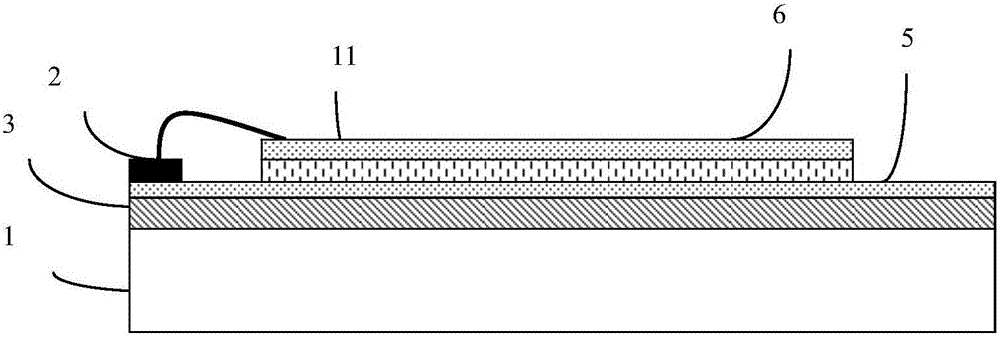
[0033] Such as figure 1 As shown, the heat sink-insulated liquid-cooled semiconductor laser of the present invention is mainly composed of a heat sink, a laser chip, a first insulating layer, a first conductive and heat-conducting layer, and a negative electrode copper sheet. The first insulating layer insulates the heat sink from the laser chip, and the first conductive and heat-conducting layer on the first insulating layer respectively arranges the laser chip and the negative electrode copper sheet at different positions, wherein the positive surface of the laser chip is directly bonded to the first conductive and heat-conducting layer. layer, an insulating interlayer exists between the negative electrode copper sheet and the surface of the first conductive and heat-conducting layer, and the negative electrode copper sheet is connected to the negative electrode surface of the laser chip through a gold wire.

[0034] The heat sink material is preferably copper, and the first...


PUM


Abstract

The invention provides a heat sink insulated liquid refrigeration semiconductor laser and a stack array thereof, which are used for meeting the requirements of high power, environmental suitability, reliability and the like. In the heat sink insulated liquid refrigeration semiconductor laser, a first insulation layer is arranged on the upper surface of a liquid refrigerator, a first electric and heat conduction layer is arranged on the first insulation layer, a laser chip and a negative electrode copper sheet are arranged at different positions of the electric and heat conduction layer, a positive surface of the laser chip is directly boned with a first electric and heat conduction layer, an insulation isolation layer exists between the negative electrode copper sheet and the surface of the first electric and heat conduction layer, and the negative electrode copper sheet is connected with a negative electrode of the laser chip through a gold wire or is directly connected with the negative electrode of the laser chip.

Description

technical field [0001] The invention relates to a liquid cooling semiconductor laser. Background technique [0002] At present, the packaging structure of semiconductor lasers is mainly divided into two types: liquid cooling type and conduction cooling type. Due to the limitation of heat dissipation principle, the conduction cooling type is also limited in power realization, and it is difficult to realize high-power devices. Liquid-cooled semiconductor laser packaging structure is currently the main choice for realizing high-power devices. [0003] Liquid-cooled semiconductor laser packaging structures mainly include two types: micro-channel and macro-channel: [0004] 1) Micro-channel liquid-cooled semiconductor lasers can achieve higher power because the micro-channel heat sink dissipates heat very well (there are tiny heat dissipation channels inside), but due to the charged work of the heat sink, there is electrochemical corrosion, which leads to long-term use There is...

Claims


Application Information

Patent Timeline
Patent Type & Authority Applications(China)
IPC IPC(8): H01S5/02H01S5/024H01S5/40
CPCH01S5/02H01S5/024H01S5/02423H01S5/40H01S5/4025
Inventor 刘兴胜于冬杉梁雪杰张林博贾阳涛
Owner FOCUSLIGHT TECH
Why Eureka
Try Eureka