A kind of multilevel inverter

A multi-level inverter and inverter technology, applied in the field of electronics, can solve the problems of high voltage stress of bridge arm power tubes, a large number of power devices, complicated control and driving, etc., so as to reduce device costs and improve power quality. , the effect of reliable work

Active Publication Date: 2016-08-17
HUAWEI DIGITAL POWER TECH CO LTD
View PDF5 Cites 0 Cited by
  • Summary
  • Abstract
  • Description
  • Claims
  • Application Information

AI Technical Summary

Problems solved by technology

However, a large number of power devices are required, and the control and driving are more complicated and expensive. Moreover, this five-level inverter has evolved from the basic T-shaped three-level inverter, and the voltage stress of the power tube of the bridge arm is relatively high.

Method used


Image

  • A kind of multilevel inverter
  • A kind of multilevel inverter

Examples


Embodiment 1

[0025] An embodiment of the present invention provides a multi-level inverter. The multi-level inverter in this embodiment is suitable for a single-phase inverter circuit, and can also be a three-phase inverter circuit, with or without a neutral line. Linear inverter system. For the convenience of description, this embodiment takes a single-phase inverter circuit as an example for detailed description, and the three-phase circuit is similar to this.

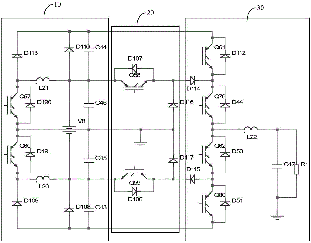
[0026] A multi-level inverter may specifically include: a bidirectional boost converter 10, a low DC bus module 20, and an I-type inverter 30, and the I-type inverter 30 is obtained according to a three-level topology; a bidirectional boost conversion The device 10 is used to output the high DC bus voltage to the I-type inverter 30; the low DC bus module 20 is used to receive the DC voltage input by the DC power supply, and output the low DC bus voltage to the I-type inverter 30; the I-type inverter The converter 30 is used to r...

Embodiment 2

[0041]The technical solution of the present invention will be described in detail below with a specific application example. Wherein, the inverter is suitable for a single-phase inverter circuit, a three-phase inverter circuit, and an inverter system with or without a neutral line. For the convenience of description, this embodiment takes a single-phase inverter circuit as an example for detailed description, and the three-phase circuit is similar to this. For details, please refer to figure 1 or figure 2 :

[0042] figure 1 Among them, Q61, Q79, Q62, and Q80 form the vertical bridge arm of the I-type structure, and its input is the high DC bus, and the low DC bus input is realized through Q58, Q59, D114, and D115, and D116 and D117 are the clamping diodes of the I-type topology , to achieve continuous flow function.

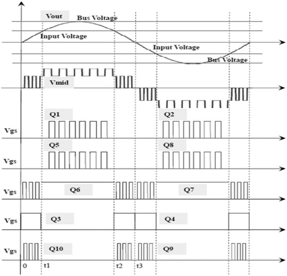
[0043] According to the level of the DC input voltage, the inverter can work in a high DC voltage mode or a low DC voltage mode, wherein, in the high DC v...


PUM


Abstract

The embodiment of the present invention discloses a multi-level inverter. The method of the embodiment of the present invention includes: a bidirectional boost converter, a low DC bus module and an I-type inverter, where the I-type inverter is obtained according to a three-level topology; the bidirectional boost converter is used to output a high-voltage output to the I-type inverter DC bus voltage; the low DC bus module is used to receive the DC voltage input by the DC power supply and output the low DC bus voltage to the I-type inverter; the I-type inverter is used to receive the high DC bus voltage output by the bidirectional boost converter, and / or the low DC bus voltage output by the low DC bus module and converted to AC output to the load. Based on the I-type three-level topology, the present embodiment realizes the multi-level operation of the converter in different modes by adding the form of a low-DC bus module branch, with a simple structure and reliable operation.

Description

technical field [0001] The invention relates to the field of electronics, in particular to a multilevel inverter. Background technique [0002] A conventional inverter is mainly composed of a rectifier, an inverter, and a charger. The rectifier is used to realize the input PFC function in the mains power mode, and to increase the battery voltage to the BUS voltage in the battery discharge mode; the charger is used to realize the mains power supply. The function of charging the battery in the mode; and the inverter is used to convert the DC BUS voltage into AC voltage, and then provide it to the load. [0003] The inverter system in the prior art realizes the function of the inverter through the following methods: using a five-level inverter based on T-shaped three-level improvement, using a bidirectional switch freewheeling bridge arm, and using double busbars to realize output The sine wave voltages are superimposed to obtain a five-level output midpoint voltage. However,...

Claims


Application Information

Patent Timeline
Patent Type & Authority Patents(China)
IPC IPC(8): H02M7/483H02M7/5387
Inventor 胡炎申
Owner HUAWEI DIGITAL POWER TECH CO LTD
Why Eureka
Try Eureka