
Spherical particle spectrum complex refractive index measurement method based on short pulse laser transmitted and reflected signals

A technology of short-pulse laser and complex refractive index, which is applied in the direction of measuring devices, particle and sedimentation analysis, particle size analysis, etc., can solve the problems of low accuracy and complicated measurement process, and achieve improved accuracy, simple measurement process and high precision Effect

Active Publication Date: 2014-01-01
HARBIN INST OF TECH
View PDF2 Cites 13 Cited by
  • Summary
  • Abstract
  • Description
  • Claims
  • Application Information

AI Technical Summary

Problems solved by technology

[0005] The present invention solves the problems of complex measurement process and low precision in the existing method for measuring spectral complex refractive index of spherical particles

Method used


Image

  • Spherical particle spectrum complex refractive index measurement method based on short pulse laser transmitted and reflected signals
  • Spherical particle spectrum complex refractive index measurement method based on short pulse laser transmitted and reflected signals
  • Spherical particle spectrum complex refractive index measurement method based on short pulse laser transmitted and reflected signals

Examples


specific Embodiment approach 1

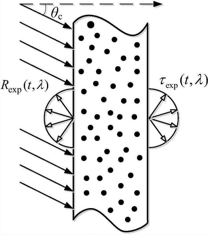
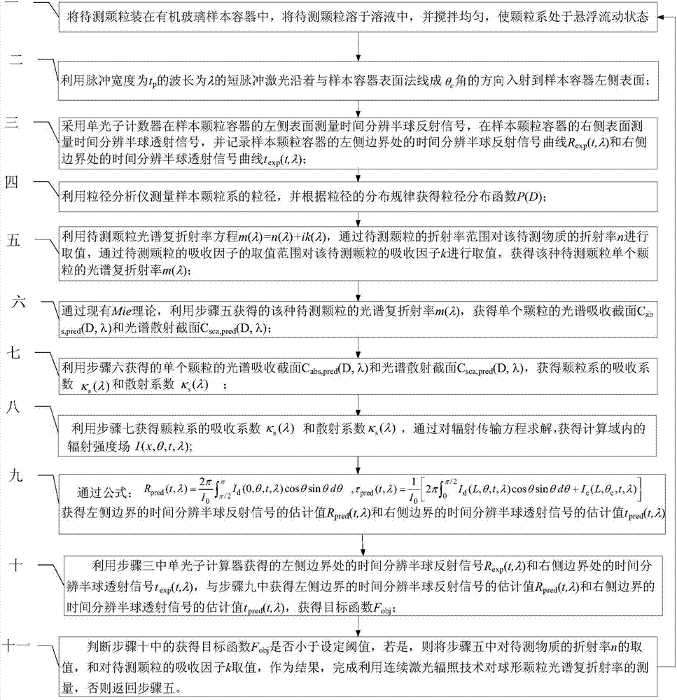
[0029] Specific implementation mode 1. Combination figure 1 , figure 2 with image 3 Describe this embodiment, this embodiment is a method for measuring the spectral complex refractive index of spherical particles based on the short-pulse laser transflective signal, the specific steps of the method are:

[0030] Step 1. Put the particles to be tested in a plexiglass sample container, dissolve the particles to be tested in the solution, and stir evenly, so that the particles are in a state of suspension and flow;

[0031] Step 2, using the pulse width as t p The short pulse laser with a wavelength of λ is along the angle θ with the surface normal of the sample container c The direction of the angle is incident on the left surface of the sample container; where, 10 -12 ≤t p ≤10 -9 s,

[0032] 0c <π / 2,0.3μm<λ<2.5μm;

[0033] Step 3: Use a single photon counter to measure the time-resolved hemispherical reflection signal on the left surface of the sample particle containe...

specific Embodiment approach 2

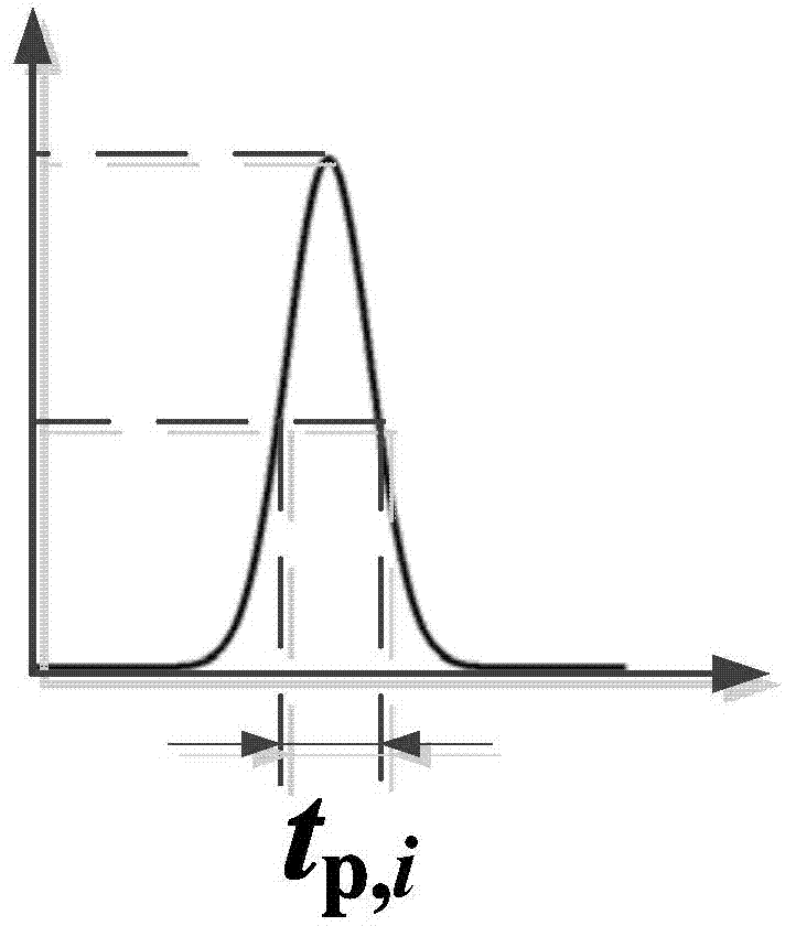
[0050] Specific embodiment 2. This embodiment is a further description of a method for measuring the spectral complex refractive index of spherical particles based on short-pulse laser transflective signals described in specific embodiment 1. The pulse width described in step 2 is t p The radiation intensity I of a short-pulse laser with a wavelength of λ c (t,λ) is:

[0051] I c ( t , λ ) = I 0 ( λ ) exp [ - 4 ln 2 ( t - 3 t p t ...

specific Embodiment approach 3

[0053] Specific embodiment 3. This embodiment is a further description of a method for measuring the spectral complex refractive index of spherical particles based on short-pulse laser transflective signals described in specific embodiment 1 or specific embodiment 2. In step 7, the particle system is obtained The absorption coefficient κ a (λ) and scattering coefficient κ s (λ) is, through the formula:

[0054] κ a ( λ ) = ∫ D min D max dD × N 0 × P ( D ) × C abs , pred ( D , λ ) - -...


PUM


Abstract

Belonging to the technical field of particle optical property measuring, the invention provides a spherical particle spectrum complex refractive index measurement method based on short pulse laser transmitted and reflected signals, and solves the problems of complex measuring process and low accuracy still existing in current spherical particle spectrum complex refractive index measurement methods. The method disclosed in the invention uses short pulse laser to irradiate a uniform spherical particle system, measures the reflected signal and transmitted signal of the particle system, employs a particle size analyzer to measure the particle size distribution of the particle system, utilizes a Mie theoretical model and inversion of a particle swarm optimization algorithm to obtain the spectrum complex refractive index of particles. The method provided in the invention is suitable for measuring the spectrum complex refractive index of particles.

Description

technical field [0001] The invention belongs to the technical field of particle optical characteristic measurement. Background technique [0002] In nature and industrial production, many substances and products are in the form of particles. According to statistics, more than 50% of the products and intermediates in the industry are in the form of particles. The absorption, scattering and emission properties of particles play an important role in many engineering and environmental systems, so it is particularly important to solve the spectral complex refractive index of particles. The spectral complex refractive index of particles belongs to the basic physical parameters of particles, which is related to the composition of particles, temperature level and surface conditions. However, the spectral complex refractive index of particles cannot be directly measured through experiments, and is usually calculated by using some experimentally measured parameters combined with rela...

Claims


Application Information

Patent Timeline
IPC IPC(8): G01N15/00G01N15/02
Inventor 贺振宗齐宏任亚涛孙双成阮立明谈和平
Owner HARBIN INST OF TECH
Learn More