
Positioning method of image sensor group

A technology of image sensor and positioning method, which is applied in the input/output process of instruments, data processing, electrical digital data processing, etc., and can solve the problems of falling, increasing difficulty of image joining, image deformation, etc.

Active Publication Date: 2016-09-07
TECO IMAGE SYST
View PDF4 Cites 0 Cited by
  • Summary
  • Abstract
  • Description
  • Claims
  • Application Information

AI Technical Summary

Problems solved by technology

However, when the installation position of any image sensor is shifted, the final spliced ​​image will be distorted
Moreover, if the screen has a curvature, the difficulty of image splicing is relatively increased
[0006] Therefore, how to realize large-screen detection and avoid image distortion and sensitivity reduction is an urgent issue to be solved.

Method used


Image

  • Positioning method of image sensor group
  • Positioning method of image sensor group
  • Positioning method of image sensor group

Examples


Embodiment Construction

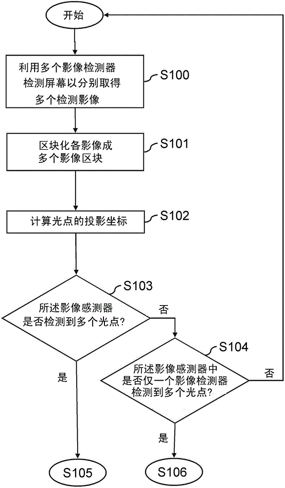
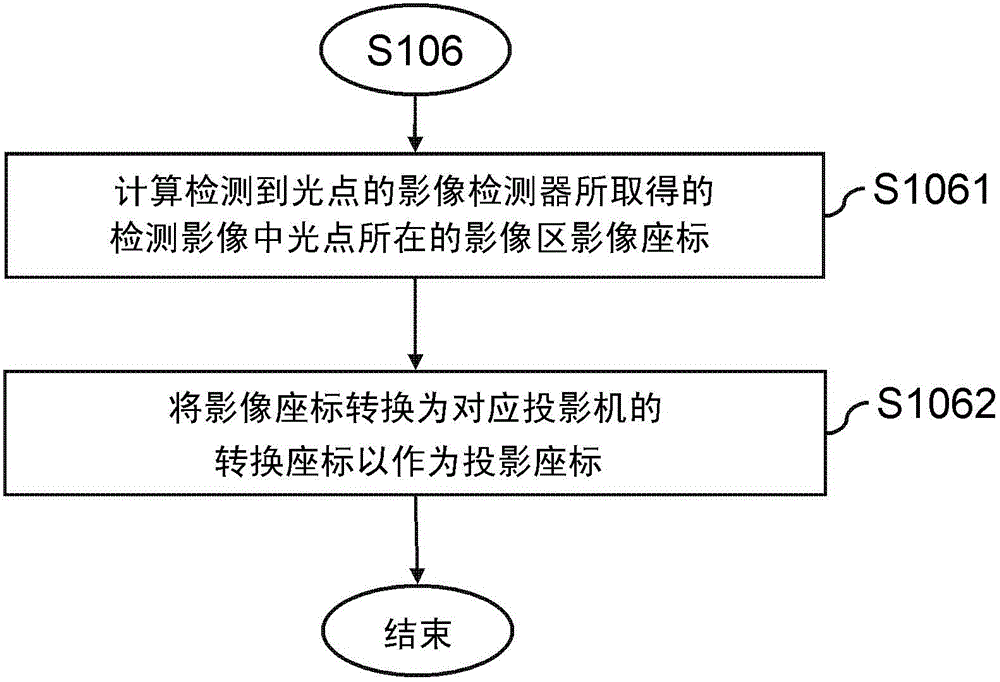
[0037] Figure 1 to Figure 3 It is a flow chart of the positioning method of the image sensor group according to the first embodiment of the present invention

[0038] refer to figure 1 , the positioning method of the array image sensor includes: using a plurality of image sensors to detect a screen with light spots to respectively obtain a plurality of sensing images (S100); block each sensing image into a plurality of image areas Block (S101); calculate projected coordinates of the light spot (S102).

[0039] In some embodiments, each sensing image is blockized into an array of image blocks.

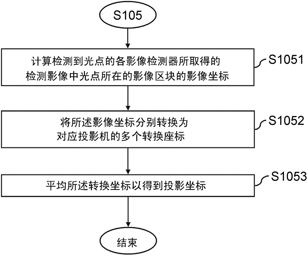
[0040] refer to figure 2 , when a plurality of the image sensors detect light spots (S105), the step of calculating the projected coordinates includes: calculating the light spots in the sensing image obtained by each image sensor that detects the light spots The image coordinates of the image block (S1051), converting these image coordinates into a plurality of transformation co...


PUM


Abstract

A method for locating an image sensor group includes using a plurality of image sensors to detect a screen with light spots to respectively obtain a plurality of sensing images, block each sensing image into a plurality of image blocks, and Computes the projected coordinates of the light point. When more than two image sensors detect light points, calculate the image coordinates of the image blocks where the light points are located in the sensing images obtained by these image sensors, and convert these image coordinates into corresponding The transformed coordinates of the projector, and averaging these transformed coordinates to obtain the projected coordinates. When only one image sensor detects the light point, calculate the image coordinates of the image block where the light point is located in the sensing image obtained by the image sensor, and convert the image coordinates into the conversion coordinates of the corresponding projector as projected coordinates.

Description

technical field [0001] The invention relates to an image positioning method, in particular to a positioning method of an image sensor group. Background technique [0002] In an optical projection system, it is impractical if the user has to input commands through a touch interface such as a touch pad or a touch panel. Therefore, if the user can directly perform system operations on the screen of the projection system by projecting laser light spots, it can not only subvert the traditional keyboard input method, but also greatly enhance the convenience of using the projection system. [0003] In the optical projection system, system operations are performed by detecting touch commands such as laser light spots and ultrasonic waves. The positioning methods for touch commands can be divided into optical positioning and acoustic positioning. When positioning with sound waves, the coordinate position of the touch command is calculated by using the sound wave to meet the soft ma...

Claims


Application Information

Patent Timeline
Patent Type & Authority Patents(China)
IPC IPC(8): G06F3/042
Inventor 陈长威朱哲田
Owner TECO IMAGE SYST
Learn More