Deformation reflector antenna phase center correction method based on far field

A technology of antenna phase center and reflective surface, applied in the direction of antenna, electrical components, etc., to achieve the effect of simple operation

Inactive Publication Date: 2014-01-01
XIDIAN UNIV
View PDF3 Cites 6 Cited by
  • Summary
  • Abstract
  • Description
  • Claims
  • Application Information

AI Technical Summary

Problems solved by technology

[0005] The purpose of the present invention is to overcome the deficiencies of the above existing methods, and propose a method for correcting the phase center of the deformed reflector antenna based on the far field, so as to realize the adjustment of the feed source or the secondary surface when the deformation of the reflector is unknown, and complete the adjustment of the antenna phase. Compensation of main surface deformation

Method used


Image

  • Deformation reflector antenna phase center correction method based on far field
  • Deformation reflector antenna phase center correction method based on far field
  • Deformation reflector antenna phase center correction method based on far field

Examples


Embodiment Construction

[0040] The present invention will be further described below in conjunction with accompanying drawings and examples of implementation.

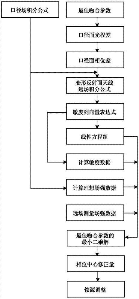
[0041] refer to figure 1 , the present invention is based on the far-field deformation reflector antenna phase center correction method, and its implementation steps are as follows:

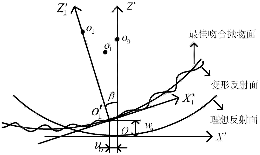
[0042] Step 1, using the best matching parameters of the deformed reflective surface, the total optical path difference of the aperture surface of the best matching paraboloid is established.

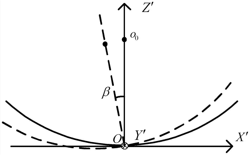
[0043] figure 2 A schematic diagram of the best matching paraboloid OX'Z' plane of the reflector antenna is given. In the figure, OX'Z' is the coordinate system whose origin is located at the fixed point of the ideal reflector, and OX' 1 Z' 1 is the coordinate system whose origin is at the fixed point of the best fitting paraboloid, o 0 is the focus of the ideal reflector, o 1 is the feed position after antenna deformation, o 2 is the focus of the best fitting para...


PUM


Abstract

The invention discloses a deformation reflector antenna phase center correction method based on a far field. The method mainly solves the problems that in the prior art, structure deformation simulation is not accurate and experience on which feed source adjustment can rely is not enough. According to the technical scheme, firstly, phase difference of a deformation reflector aperture face is expressed with a best matching parameter; secondly, the phase difference is put into a far field calculation formula and expanded on the basis of a first order of Taylor series, and sensitivity of antenna far filed intensity to the best matching parameter is deduced; thirdly, according to the sensitivity information, the far field intensity and the best matching parameter form a linear equitation system; according to the measured far filed intensity, the linear equitation system is solved on the basis of an MATLAB left dividing operation, and a least square solution of the best matching parameter is obtained; fifthly, according to the least square solution, phase center correction amount is calculated, and feed source adjustment is guided. The deformation reflector antenna phase center correction method based on the far field can effectively calculate the phase center adjustment amount of a deformation reflector antenna and be used for adjusting a feed source of the deformation reflector antenna.

Description

technical field [0001] The invention relates to the technical field of antennas, in particular to a method for correcting the phase center of a deformed reflector antenna based on a far field. Applied to phase center correction or feed adjustment of deformed reflector antenna. Background technique [0002] Microwave antenna is a typical electromechanical combination equipment, and reflector antenna is the most widely used one. With the development of science and technology, planar antennas are developing in the direction of high frequency, high gain, and large aperture. The deformation caused by external loads, such as heat, gravity, and wind, seriously deteriorates the electrical performance of the antenna. [0003] In order to ensure the electrical performance of the antenna, certain measures must be taken to reduce the influence of the deformation of the reflector on the electrical performance. The simplest compromise method is to find a reasonable panel installation ad...

Claims


Application Information

Patent Timeline
IPC IPC(8): H01Q19/10H01Q3/32
Inventor 连培园王伟段宝岩朱敏波李鹏张逸群许万业胡乃岗杨癸庚
Owner XIDIAN UNIV
Why Eureka
Try Eureka