
Cable shield connection method and structure

A technology of cable shielding and connection structure, which is applied in the direction of connection, parts and circuits of connection devices, etc. It can solve the problems of damage to the insulation layer, impact on the life of cables and electrical connectors, and the inability to adjust special connection parts and titanium-nickel alloy rings, etc. , to achieve the effect of meeting the correct termination conditions, eliminating oxidation and corrosion, and good industrial applicability

Inactive Publication Date: 2014-01-01
BEIJING INST OF SPACE LAUNCH TECH +1
View PDF10 Cites 0 Cited by
  • Summary
  • Abstract
  • Description
  • Claims
  • Application Information

AI Technical Summary

Problems solved by technology

Utilizing the shielding connection method of the titanium-nickel alloy ring and the insulating sleeve, the inner diameter of the titanium-nickel alloy ring must match the outer diameter of the cable shield after the heat-shrinkable tube tail cover is used, and the special connection parts and the titanium-nickel alloy ring cannot Adjusts with the change of the outer diameter of the cable, so the choice is limited
In addition, the storage and transportation temperature should not be higher than 50°C, otherwise shrinkage will occur, which will cause extrusion of the cable, which will affect the change of the thickness of the semi-conductive layer for a long time, and even damage the insulating layer, which will have a great impact on the life of the cable and electrical connector. Big
Therefore, a new shielding method is currently needed to solve the problem that the size of the special component must match the outer diameter of the heat-shrinkable tail-shield during the shielding process of the electrical connector and is limited by temperature.

Method used

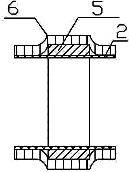
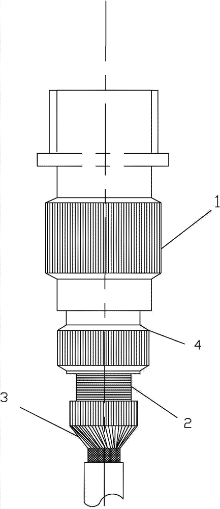
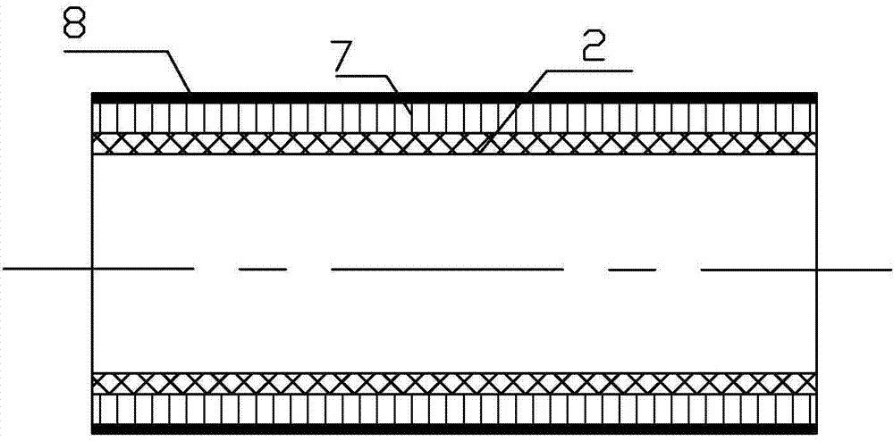

Image

  • Cable shield connection method and structure
  • Cable shield connection method and structure
  • Cable shield connection method and structure

Examples


Embodiment Construction

[0019] The specific embodiment of the present invention is described in detail below in conjunction with accompanying drawing:

[0020] Such as figure 2 As shown, in one embodiment of the cable shielding connection method and structure of the present invention, it includes an electrical connector 1 and a heat-shrinkable tube type tail cover 4 connected to the electrical connector 1, and the heat-shrinkable tube type tail cover 4 includes a There are nuts, round tubes and connectors. There are external threads on the outer wall of the round tube, and a nut with internal threads is movably connected to the upper end. The electric connector 1 and the heat-shrinkable tube type tail cover 4 are reliably connected through the nut. The lower end of the round pipe is fixed with a connecting piece, and the lower end of the connecting piece is connected with a cable.

[0021] The cable shielding 2 on the outer layer of the cable is in the form of a mesh, and the cable shielding 2 cove...


PUM

PropertyMeasurementUnit
Diameteraaaaaaaaaa
Thicknessaaaaaaaaaa

Abstract

The invention relates to a cable shield connection method and structure and discloses an electric connector heat-shrinking tube type tail cover 360-degree shielding method which adapts to fields and is low in cost, high in reliability and easy to operate. The cable shield connection method and structure is characterized in that thin copper wires are wound on a cable shield on a heat-shrinking tube type tail cover of an electric connector by means of a stranding and spaced-winding method till the copper wires cover the cable shield, then tin coating is performed on the surfaces of copper wire loops to enable the copper wires to be reliable, tight and firm, and the cable shield is fixed so that the cable shield cannot slips from the tail cover. The cable shield connection method is simple in operation, has no the strict tolerance size requirement of general titanium-nickel alloy rings and can achieve the purpose of cable 360-degree shielding protection.

Description

technical field [0001] The invention relates to a cable connection method and structure, in particular to a shielding connection method and structure of an electric connector tail cover. Background technique [0002] As we all know, electromagnetic interference exists in two ways, namely radiated interference and conducted interference. For radiated interference, shielding is used for protection, and for conducted interference, filtering is the main means of protection. As an important part of electronic signal transmission, transmission cables and electrical connectors should have good transmission characteristics and electromagnetic compatibility, and various electromagnetic interference is the most serious at the interface, which is the window for EMI to enter and exit. [0003] When the insulated conductor is covered with a wire braid or metal film, it is called a shielded wire. When several insulated conductors are combined into a bundle, and the outside is wrapped wit...

Claims


Application Information

Patent Timeline
IPC IPC(8): H01R13/6593H01R43/00
Inventor 尚维琦袁皓宋建琦王磊赵龙飞余小勇毕煌鑫
Owner BEIJING INST OF SPACE LAUNCH TECH
Learn More