Syringe head, ejector unit, and syringe formed from same

A technology for syringes and syringe barrels, applied in the directions of syringes, ampoule syringes, hypodermic injection devices, etc., can solve the problems of not getting the position of the needle end, no longer guaranteeing the sealing sterility, displacement of the joints, etc. Possibility of operation, improvement of work reliability, effect of guide prevention

Inactive Publication Date: 2014-01-01
PHARMA CONSULT GMBH & CO NFG KG
View PDF8 Cites 5 Cited by
  • Summary
  • Abstract
  • Description
  • Claims
  • Application Information

AI Technical Summary

Problems solved by technology

Here again the disadvantage is that the guide pins are arranged on the inner side of the guide sleeve, which is complex to produce and is associated with a high scrap rate
However, there is likewise no defined end position positioning of the needle with its needle ho

Method used


Image

  • Syringe head, ejector unit, and syringe formed from same
  • Syringe head, ejector unit, and syringe formed from same
  • Syringe head, ejector unit, and syringe formed from same

Examples


Embodiment Construction

[0048] At the outset, it should be noted that in the various embodiments of the different descriptions the same parts are assigned the same reference symbols or the same component designations, and that the disclosure contained in the entire description can be transferred to on the same part of the name. Furthermore, selected position indications such as top, bottom, side, etc. in the description refer to the directly described and illustrated figures and are intended to be transferred to the new position when the position is changed.

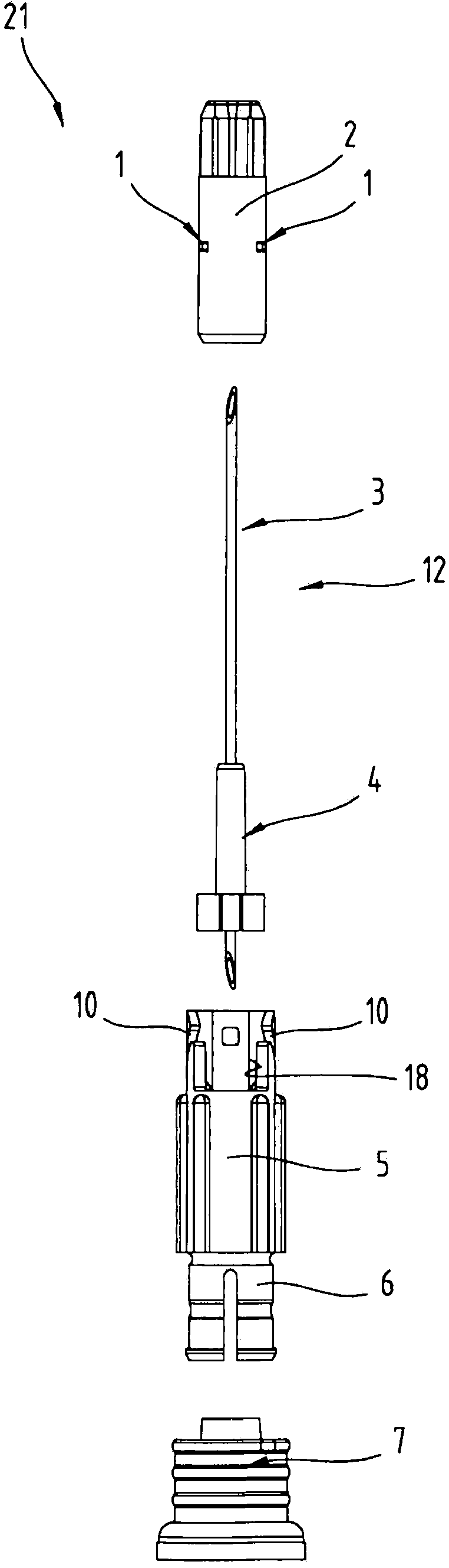
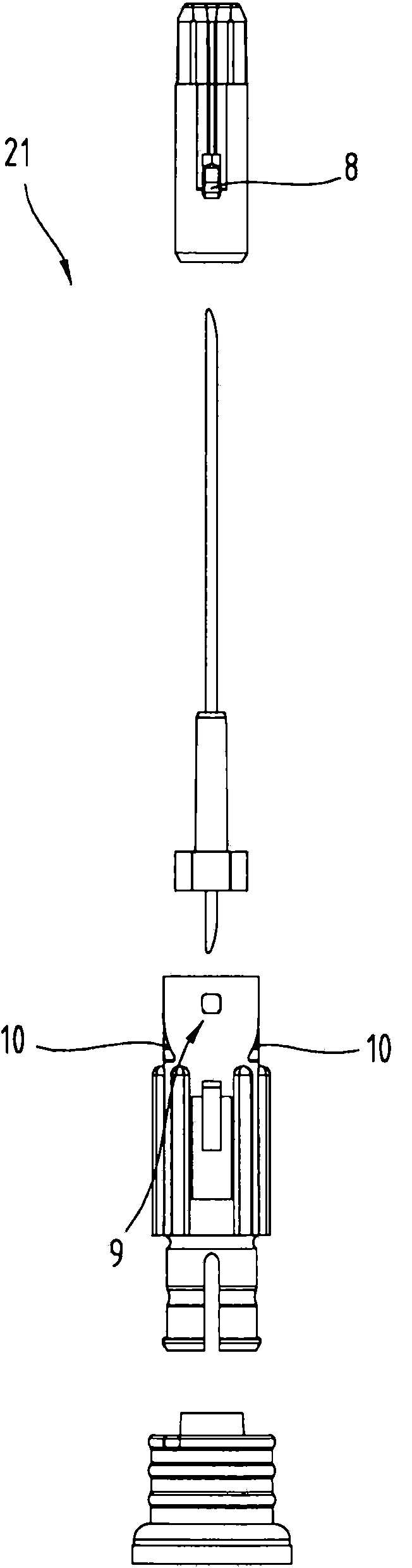
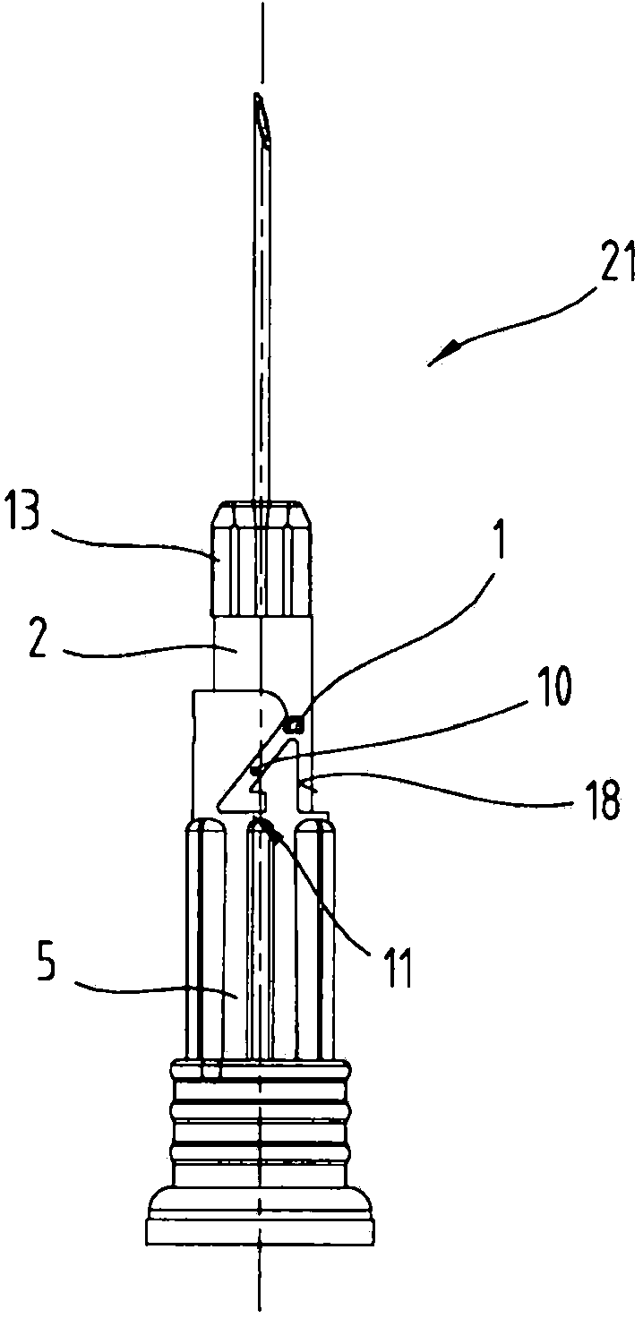
[0049] according to figure 1 , the syringe head 21 has a needle unit 12 with a needle 3 and a needle seat 4 . The needle unit 12 is mounted in the guide sleeve 5 . The needle unit 12 is driven in the direction of the syringe barrel (not shown) by the drive element 2 , which is slipped onto the needle unit 12 , in order to connect the needle 3 to the sealed syringe barrel immediately prior to injection. The drive element 2, the needle holder ...


PUM


Abstract

The invention relates to a syringe head (21) for a syringe (20), with a needle unit (12), which is arranged in a guide sleeve (5) and is slidable therein, and with a pinion (2), by means of which the needle unit (12) is axially movable, relative to a syringe barrel (15), from a rest position to an actuation position. The pinion (2) has at least one guide knob (1), which can be brought into engagement optionally with one of two slotted-guide tracks (10) provided in the guide sleeve (5), wherein the slotted-guide tracks (10) have opposite inclinations. Furthermore, the invention also relates to an ejector unit (25), and to a syringe (20) having a syringe barrel (15), the syringe head (21) and the ejector unit (25).

Description

technical field [0001] The invention relates to an injector head for an injector, which has a needle unit which is arranged in a guide sleeve and is slidably movable in the guide sleeve, and a drive element, by means of which the needle unit is axially opposed to each other. Because the syringe barrel is movable from an initial position to an activated position. Background technique [0002] In this description, the directions "proximal" and "distal" are defined as viewed from the side of the patient. Thus, in the components described below, the proximal side is always the side facing the patient and the distal side is always the side facing away from the patient. Syringes, especially disposable syringes, are known devices for injecting medicaments. In disposable syringes, which are often used by patients themselves, the needle is connected to the syringe barrel just before use by turning the needle. [0003] A syringe head is known from AT404430B, in which the needle pie...

Claims


Application Information

Patent Timeline
IPC IPC(8): A61M5/28A61M5/32A61M5/24
CPCA61M2005/312A61M5/3234A61M5/345A61M5/508A61M5/288A61M5/347A61M5/502A61M5/322A61M2005/3139A61M2005/3238A61M2005/3235A61M5/3202A61M5/2466A61M2005/2474
Inventor E·皮克哈德A·施维茨
Owner PHARMA CONSULT GMBH & CO NFG KG
Why Eureka
Try Eureka